


English-8
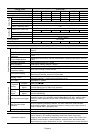
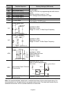
Terminal
Symbol
Terminal Function Factory Settings (NPN mode)
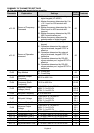
M0 Multi-function auxiliary input
M1 Multi-function input 1
M2 Multi-function input 2
M3 Multi-function input 3
M4 Multi-function input 4
M5 Multi-function input 5
M0~M5-GND
Refer to P38~P42 for programming the multi-function
inputs.
ON: the activation current is 10 mA.
OFF: leakage current tolerance is 10
μ
A.
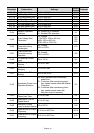
GND Common Signal
+10V +10 Vdc Output
+10V-GND
It can supply +10 VDC power.
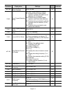
AVI
Analog Voltage Input
ACM
AVI
+10V
Internal Circuit
AVI Circuit
Impedance: 20kΩ
Resolution: 10 bits
Range: 0~10Vdc = 0~Max.Output Frequency
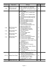
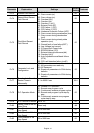
ACI
Analog Current Input
ACM
ACI
Internal Circuit
ACI Circuit
Impedance: 250Ω
Resolution: 10 bits
Range: 4~20mA = 0~Max.Output Frequency
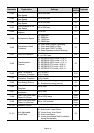
AFM
Analog Output Meter
Internal Circuit
ACM Circuit
AFM
ACM
0~10V
Potentiometer
Max. 2mA
0 to 10V, 2mA
Impedance: 100kΩ
Output Current: 2mA max
Resolution: 8 bits
Range: 0 ~ 10Vdc
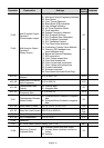
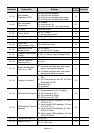
MO1
Multi-function Output Terminal
(Photocoupler)
Maximum: 48Vdc, 50mA
Refer to P45 for programming.
MO1-DCM
MO1
MCM
Internal Circuit
Max: 48Vdc/50mA
MCM
Multi-function Output Common
(Photocoupler)
Common for Multi-function Outputs
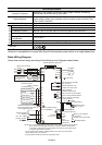
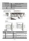
Note: Use twisted-shielded, twisted-pair or shielded-lead wires for the control signal wiring. It is
recommended to run all signal wiring in a separate steel conduit. The shield wire should only be
connected at the drive. Do not connect shield wire on both ends.