


English-12
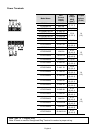
Parameter Explanation Settings
Factory
Setting
Customer
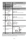
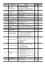
Pr.45
Pr.46
Multi-Function Output
Terminal 1
(Photocoupler output)
Multi-function Output
Terminal 2
(Relay Output)
00: AC Drive Operational
01: Maximum Output Frequency Attained
02: Zero Speed
03: Over-Torque Detection
04: Base-Block (B.B) Indication
05: Low Voltage Indication
06: AC Drive Operation Mode
07: Fault Indication
08: Desired Frequency Attained
09: PLC Program Running
10: PLC Program Step Completed
11: PLC Program Completed
12: PLC Operation Paused
13: Top Count Value Attained
14: Preliminary Counter Value Attained
15: Warning (PID feedback loss,
communication error)
16: Below the Desired Frequency
17: PID supervision
18: Over Voltage supervision
19: Over Heat supervision
20: Over Current stall supervision
21: Over Voltage stall supervision
22: Forward command
23: Reverse command
24: Zero Speed (Includes Drive Stop)
00
07
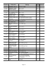
aPr.47
Desired Frequency
Attained
0.00 to 400.0 Hz 0.00
aPr.48
Adjust Bias of External
Input Frequency
0.00 to 200.0% 0.00
aPr.49
Potentiometer Bias
Polarity
00: Positive Bias
01: Negative Bias
00
aPr.50
Potentiometer
Frequency Gain
0.10 to 200.0% 100.0
Pr.51
Potentiometer Reverse
Motion Enable
00: Reverse Motion Disabled in negative
bias
01: Reverse Motion Enabled in negative
bias
00
aPr.52 Motor Rated Current 30.0% FLA to 120.0% FLA FLA
aPr.53 Motor No-Load Current 00%FLA to 99%FLA
0.4*
FLA
aPr.54 Torque Compensation 00 to 10 00
aPr.55 Slip Compensation 0.00 to 10.00 0.00
Pr.56 Reserved
Pr.57 AC Drive Rated Current Display (unit: 0.1A) ##.#
Pr.58
Electronic Thermal
Overload Relay
00: Standard Motor (self cool motor)
01: Inverter Motor (auxiliary cool fan on
motor)
02: Inactive
02