


Dell
PowerEdge R510 Technical Guide 22
The Power LED has two states:
• Power LED is OFF: System is not operating, regardless of AC present. (Other AUX powered subsystems
may be operational with AC power present.)
• Power LED is ON (Green): System is operating. One or more of the non-standby (Vaux) power rails are
active.
All PowerEdge servers include a green colored LED on the motherboard to indicate the presence of standby
power (Vaux). This LED is in a visible location for service personnel. Some server operating systems allow
users to configure the function of the power button through the ACPI feature.
The system has the capability to remember the state of the Power button prior to AC loss (option selected
through BIOS setup). If this option is enabled via BIOS setup, system power returns to the state prior to AC
loss with the resumption of AC.
If the power button is disabled through system management mechanisms, the user can shut down the system
during a crash (regardless of the Power button enable/disable settings).
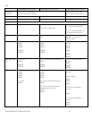
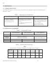
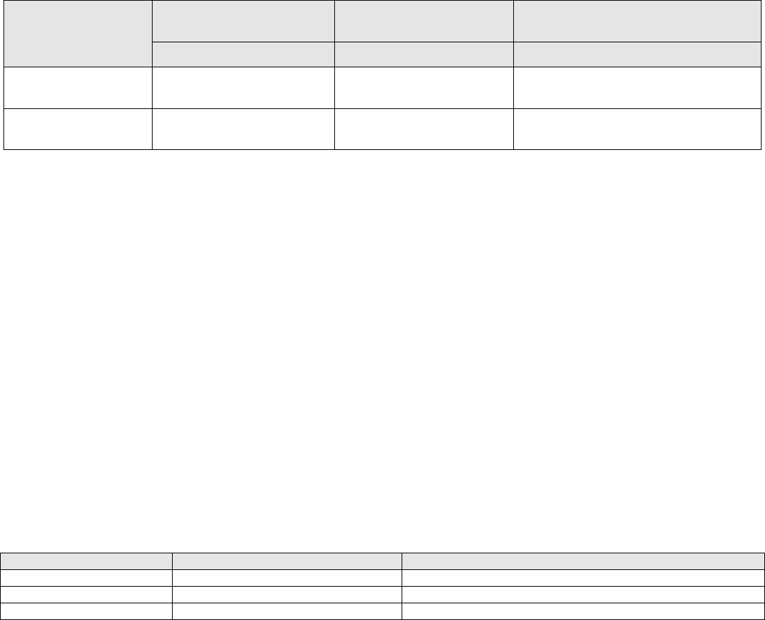
Table 6. Power Button Behavior under ACPI/Non-ACPI Operating Systems
Action
ACPI OS w/ACPI Enabled
Non-ACPI OS or ACPI OS
w/ ACPI Disabled
ACPI or Non-ACPI OS
System Turned ON
System Turned ON
System Turned OFF
Press and release
power button
System performs a graceful
shutdown
System turns off
Boots
Hold power button for
6 seconds
System turns off
System turns off
System starts and shuts down 6
seconds later.
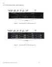
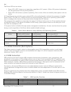
4.3.4 Video Connector (Rack Systems)
The video connector is used to attach a video graphics array (VGA)-compatible monitor to rack-based
systems. Space around the connector accommodates full usage of it with all adjacent interfaces (USB
connectors, button, LED’s, etc.).
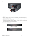
4.3.5 USB Connectors
USB connectors are used to attach USB-compliant devices such as keyboards, mice, storage keys, and
peripherals to the system. All PowerEdge systems have at least 2 front-accessible USB 2.0 compliant ports
spaced to accommodate full usage of both connectors simultaneously with other front panel features (e.g.,
Video connector, buttons, LEDs) without mechanical interference. These ports must be connected to the
same controller and cannot be shared with internal or back USB ports.
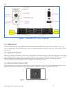
For security, all external USB ports have an enable/disable function. Internal USB ports connected to
internal persistent storage devices have an enable/disable function independent of the other ports in the
system.
Except for platforms using chipsets that allow independent control to enable/disable each USB controller,
disabling USB controllers observe the hierarchy detailed in Table 7 (listed from lowest to highest priority in a
3-controller design).
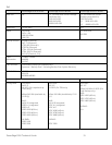
Table 7. USB Controller Priorities
USB Controller
Function
If disabled
3
Front USB
No other controller is disabled
2
Back USB
Controller 3 is disabled as well
1 (Highest)
Remote Access (RAC)
Controllers 2 & 3 are disabled as well