


Dell
PowerEdge R510 Technical Guide 6
Table 27. Microsoft Operating Systems Supported ................................................................... 65
Table 28. Linux Operating Systems .................................................................................... 66
Table 29. Supported Virtualization Operating Systems ............................................................. 67
Table 30. Unified Server Configurator Features and Description .................................................. 69
Table 31. Features List for BMC, iDRAC6, and vFlash ............................................................... 70
Table 32. Single Pack Dimensions and Weights ....................................................................... 73
Table 33. PowerEdge R510 Volatility .................................................................................. 74
Table 34. Volatility: Data Writing and Purpose ...................................................................... 76
Table 35. Methodology for Data Input to Memory ................................................................... 78
Table 36. Methodology for Memory and Clearing .................................................................... 80
Figures
Figure 1. Intel Xeon Processors 5500 and 5600 Series .............................................................. 11
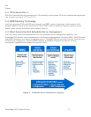
Figure 2. Embedded Server Management Capability ................................................................ 12
Figure 3. System Dimensions ........................................................................................... 19
Figure 4. PowerEdge R510–4 HDD Configuration ..................................................................... 20
Figure 5. PowerEdge R510–8 HDD Configuration ..................................................................... 20
Figure 6. PowerEdge R510–12 HDD Configuration ................................................................... 21
Figure 7. Power Button/LED Implementation ........................................................................ 21
Figure 8. Bezel Lock on Front Access Panel .......................................................................... 23
Figure 9. R510 with Non-Redundant Power Supply for PowerEdge R510-4 ONLY ............................... 24
Figure 10. With Redundant Power Supply for PowerEdge R510-8 and 12 ...................................... 24
Figure 11. Non-redundant Power Supply Option on PowerEdge R510-8 and 12 ............................... 24
Figure 12. Redundant PSU ............................................................................................. 25
Figure 13. Left Side View .............................................................................................. 25
Figure 14. Right Side View ............................................................................................ 25
Figure 15. PowerEdge R510-4: Non-Redundant PSU and the Battery Holder for PERC Card ................. 26
Figure 16. Cabled HDD, No Backplane ............................................................................... 26
Figure 17. PowerEdge R510-12 Internal View (Redundant PSU with PDB and Additional Fan for PSU) ..... 27
Figure 18. PowerEdge R510–12 Internal View ...................................................................... 27
Figure 19. R510 Sliding Rails without CMA .......................................................................... 29
Figure 20. R510 Sliding Rails with CMA .............................................................................. 29
Figure 21. R510 Static Rails ........................................................................................... 30
Figure 22. R510 Static Rails in Rack ................................................................................. 30
Figure 23. Fan Module for R510-4 and 8 ............................................................................. 31
Figure 24. Fan Module for R510-12 ................................................................................... 31
Figure 25. Fan Location ................................................................................................ 32
Figure 26. Fan Connector Locations ................................................................................. 32
Figure 27. PowerEdge R510–4 Internal USB Connector ............................................................ 34
Figure 28. PowerEdge R510–8 Internal USB Connector ............................................................ 34
Figure 29. PowerEdge R510–12 USB Connector ..................................................................... 35
Figure 30. Power Supply Connector (24 pins) ...................................................................... 36
Figure 31. Connector (8 pins) ......................................................................................... 37
Figure 32. Riser 1 ....................................................................................................... 53
Figure 33. Riser 2 ....................................................................................................... 54
Figure 34. 2.5‖ Drive in Hard Drive Carrier ......................................................................... 56
Figure 35. PowerEdge R510 Packaging .............................................................................. 73