


4
Ports A, B, and C
The 82C55A contains three 8-bit ports (A, B, and C). All can
be configured to a wide variety of functional characteristics
by the system software but each has its own special features
or “personality” to further enhance the power and flexibility of
the 82C55A.
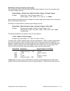
Port A One 8-bit data output latch/buffer and one 8-bit data
input latch. Both “pull-up” and “pull-down” bus-hold devices
are present on Port A. See Figure 2A.
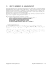
Port B One 8-bit data input/output latch/buffer and one 8-bit
data input buffer. See Figure 2B.
Port C One 8-bit data output latch/buffer and one 8-bit data
input buffer (no latch for input). This port can be divided into
two 4-bit ports under the mode control. Each 4-bit port con-
tains a 4-bit latch and it can be used for the control signal
output and status signal inputs in conjunction with ports A
and B. See Figure 2B.
Operational Description
Mode Selection
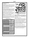
There are three basic modes of operation than can be
selected by the system software:
Mode 0 - Basic Input/Output
Mode 1 - Strobed Input/Output
Mode 2 - Bi-directional Bus
When the reset input goes “high”, all ports will be set to the
input mode with all 24 port lines held at a logic “one” level by
internal bus hold devices. After the reset is removed, the
82C55A can remain in the input mode with no additional ini-
tialization required. This eliminates the need to pullup or pull-
down resistors in all-CMOS designs. The control word
register will contain 9Bh. During the execution of the system
program, any of the other modes may be selected using a
single output instruction. This allows a single 82C55A to
service a variety of peripheral devices with a simple software
maintenance routine. Any port programmed as an output
port is initialized to all zeros when the control word is written.
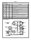
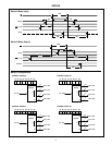
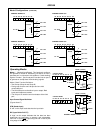
FIGURE 2A. PORT A BUS-HOLD CONFIGURATION
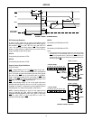
FIGURE 2B. PORT B AND C BUS-HOLD CONFIGURATION
FIGURE 2. BUS-HOLD CONFIGURATION
MASTER
RESET
OR MODE
CHANGE
INTERNAL
DATA IN
INTERNAL
DATA OUT
(LATCHED)
EXTERNAL
PORT A PIN
OUTPUT MODE
INPUT MODE
RESET
OR MODE
CHANGE
INTERNAL
DATA IN
INTERNAL
DATA OUT
(LATCHED)
EXTERNAL
PORT B, C
OUTPUT MODE
PIN
P
V
CC
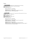
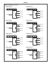
FIGURE 3. BASIC MODE DEFINITIONS AND BUS INTERFACE
DATA BUS
8 I/O
B
PB7-PB0
4 I/O
PC3-PC0
4 I/O
C
PC7-PC4
8 I/O
A
PA7-PA0
CONTROL BUS
ADDRESS BUS
RD, WR
82C55A
D7-D0 A0-A1
CS
MODE 0
8 I/O
B
PB7-PB0 CONTROL
C
8 I/O
A
PA7-PA0
MODE 1
OR I/O
CONTROL
OR I/O
8 I/O
B
PB7-PB0
C
BI-
A
PA7-PA0
MODE 2
CONTROL
DIRECTIONAL
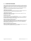
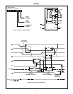
FIGURE 4. MODE DEFINITION FORMAT
D7 D6 D5 D4 D3 D2 D1 D0
PORT C (LOWER)
1 = INPUT
0 = OUTPUT
PORT B
1 = INPUT
0 = OUTPUT
MODE SELECTION
0 = MODE 0
1 = MODE 1
GROUP B
PORT C (UPPER)
1 = INPUT
0 = OUTPUT
PORT A
1 = INPUT
0 = OUTPUT
MODE SELECTION
00 = MODE 0
01 = MODE 1
GROUP A
1X = MODE 2
MODE SET FLAG
1 = ACTIVE
CONTROL WORD
82C55A