


Copyright 2001 Diamond Systems Corp. Ruby-MM-1612 User Manual V1.1 P. 4
2. I/O HEADER PINOUT
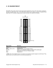
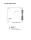
Ruby-MM-1612 provides a 50-pin right-angle header labeled J3 for all user I/O. This header is located on
the right side of the board. Pins 1, 2, 49, and 50 are marked to aid in proper orientation. A standard 50-pin
cable-mount IDC (insulation displacement contact) connector will mate with this header.
J3
(Top of board)
Agnd 1 2 Vout 0
Agnd 3 4 Vout 1
Agnd 5 6 Vout 2
Agnd 7 8 Vout 3
Agnd 9 10 Vout 4
Agnd 11 12 Vout 5
Agnd 13 14 Vout 6
Agnd 15 16 Vout 7
Vout 8 17 18 Vout 9
Vout 10 19 20 Vout 11
Vout 12 21 22 Vout 13
Vout 14 23 24 Vout 15
DIO A7 25 26 DIO A6
DIO A5 27 28 DIO A4
DIO A3 29 30 DIO A2
DIO A1 31 32 DIO A0
DIO B7 33 34 DIO B6
DIO B5 35 36 DIO B4
DIO B3 37 38 DIO B2
DIO B1 39 40 DIO B0
DIO C7 41 42 DIO C6
DIO C5 43 44 DIO C4
DIO C3 45 46 DIO C2
DIO C1 47 48 DIO C0 / Ext Trig
+5V 49 50 Dgnd
Signal Name Definition
Vout15 - 0 Analog output channels
Agnd Analog ground
DIO A7-0, B7-0, C7-0 Digital I/O lines (programmable direction)
Ext Trig Digital I/O line C0 can be used as an external D/A update signal
+5V Connected to PC/104 bus +5V power supply
Dgnd Digital ground
⇒⇒ Note: The +5V and Dgnd lines do not need to be connected to a power supply to use this board. They
are provided as connection points for convenience purposes only.