


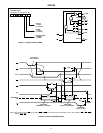

13
Special Mode Combination Considerations
There are several combinations of modes possible. For any
combination, some or all of Port C lines are used for control
or status. The remaining bits are either inputs or outputs as
defined by a “Set Mode” command.
During a read of Port C, the state of all the Port C lines,
except the
ACK and STB lines, will be placed on the data
bus. In place of the
ACK and STB line states, flag status will
appear on the data bus in the PC2, PC4, and PC6 bit
positions as illustrated by Figure 17.
Through a “Write Port C” command, only the Port C pins
programmed as outputs in a Mode 0 group can be written.
No other pins can be affected by a “Write Port C” command,
nor can the interrupt enable flags be accessed. To write to
any Port C output programmed as an output in Mode 1 group
or to change an interrupt enable flag, the “Set/Reset Port C
Bit” command must be used.
With a “Set/Reset Port Cea Bit” command, any Port C line
programmed as an output (including IBF and
OBF) can be
written, or an interrupt enable flag can be either set or reset.
Port C lines programmed as inputs, including
ACK and STB
lines, associated with Port C fare not affected by a
“Set/Reset Port C Bit” command. Writing to the correspond-
ing Port C bit positions of the
ACK and STB lines with the
“Set Reset Port C Bit” command will affect the Group A and
Group B interrupt enable flags, as illustrated in Figure 17.
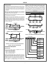
Current Drive Capability
Any output on Port A, B or C can sink or source 2.5mA. This
feature allows the 82C55A to directly drive Darlington type
drivers and high-voltage displays that require such sink or
source current.
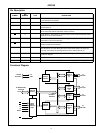
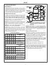
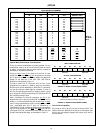
MODE DEFINITION SUMMARY
MODE 0 MODE 1 MODE 2
IN OUT IN OUT GROUP A ONLY
PA0
PA1
PA2
PA3
PA4
PA5
PA6
PA7
In
In
In
In
In
In
In
In
Out
Out
Out
Out
Out
Out
Out
Out
In
In
In
In
In
In
In
In
Out
Out
Out
Out
Out
Out
Out
Out
PB0
PB1
PB2
PB3
PB4
PB5
PB6
PB7
In
In
In
In
In
In
In
In
Out
Out
Out
Out
Out
Out
Out
Out
In
In
In
In
In
In
In
In
Out
Out
Out
Out
Out
Out
Out
Out
PC0
PC1
PC2
PC3
PC4
PC5
PC6
PC7
In
In
In
In
In
In
In
In
Out
Out
Out
Out
Out
Out
Out
Out
INTRB
IBFB
STBB
INTRA
STBA
IBFA
I/O
I/O
INTRB
OBFB
ACKB
INTRA
I/O
I/O
ACKA
OBFA
I/O
I/O
I/O
INTRA
STBA
IBFA
ACKA
OBFA
Mode 0
or Mode 1
Only
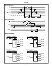
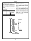
INPUT CONFIGURATION
D7 D6 D5 D4 D3 D2 D1 D0
I/O I/O IBFA INTEA INTRA INTEB IBFB INTRB
OUTPUT CONFIGURATION
D7 D6 D5 D4 D3 D2 D1 D0
OBFA INTEA I/O I/O INTRA INTEB OBFB INTRB
FIGURE 15. MODE 1 STATUS WORD FORMAT
D7 D6 D5 D4 D3 D2 D1 D0
OBFA INTE1 IBFA INTE2 INTRA X X X
(Defined by Mode 0 or Mode 1 Selection)
FIGURE 16. MODE 2 STATUS WORD FORMAT
GROUP A
GROUP B
GROUP A
GROUP B
GROUP A
GROUP B
82C55A