


Copyright 2001 Diamond Systems Corp. Ruby-MM-1612 User Manual V1.1 P. 5
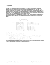
3. BOARD CONFIGURATION
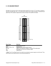
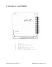
Refer to the Drawing of Ruby-MM-1612 on Page 8 for locations of headers described in Chapters 3 and
4.
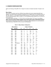
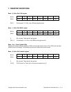
Base Address
Each board in the system must have a different base address. Use the pin header labeled J5, base
address. The numbers above the jumpers correspond to the I/O address bits; bit 9 is the MSB and bit 0 is
the LSB. Only bits 9 – 4 are used for the base address decoding. The remaining 4 bits 3-0 are assumed
to be 0 for the base address. When a jumper is in, the corresponding base address bit is a 0, and when it
is out, the bit is a 1.
The default address is 300 Hex = 1 1 0 0 0 0 0 0 0 0, so 9 8 are out and 7 6 5 4 are in. Any address
above 100 Hex is a valid I/O address. However, there are many other circuits and boards sharing the I/O
space, so you should check the documentation for your other boards to avoid conflicts. Below are some
recommended I/O addresses for Ruby-MM-1612. Although the Base addresses can only be selected on
16-byte boundaries, Ruby-MM-1612 only uses the first 8 addresses.
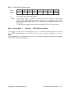
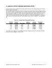
Table 3.1: Base Address Configuration
Base Address Header J5 Position
Hex Decimal 9 8 7 6 5 4
220 544 Out In In In Out In
240 576 Out In In Out In In
250 592 Out In In Out In Out
260 608 Out In In Out Out In
280 640 Out In Out In In In
290 656 Out In Out In In Out
2A0 672 Out In Out In Out In
2B0 688 Out In Out In Out Out
2C0 704 Out In Out Out In In
2D0 720 Out In Out Out In Out
2E0 736 Out In Out Out Out In
300 768 (Default) Out Out In In In In
330 816 Out Out In In Out Out
340 832 Out Out In Out In In
350 848 Out Out In Out In Out
360 864 Out Out In Out Out In
380 896 Out Out Out In In In
390 912 Out Out Out In In Out
3A0 928 Out Out Out In Out In
3C0 960 Out Out Out Out In In
3E0 992 Out Out Out Out Out In