


D-Link EasySmart Switch User Manual
8
B) Reduced Air Flow - Installation of the equipment in a rack should be such that the amount of air flow
required for safe operation of the equipment is not compromised.
C) Mechanical Loading - Mounting of the equipment in the rack should be such that a hazardous condition is
not achieved due to uneven mechanical loading.
D) Circuit Overloading - Consideration should be given to the connection of the equipment to the supply
circuit and the effect that overloading of the circuits might have on overcurrent protection and supply wiring.
Appropriate consideration of equipment nameplate ratings should be used when addressing this concern.
E) Reliable Earthing - Reliable earthing of rack-mounted equipment should be maintained. Particular
attention should be given to supply connections other than direct connections to the branch circuit (e.g. use
of power strips)."
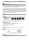
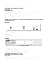
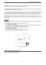
Wall-mount
The Switch can be mounted on a wall. Two mounting slots are provided on the bottom of the switch for this
purpose.
Please follow the installation steps to complete wall-mount process.
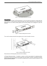
Mounting on a cement wall
Step 1: Mount the nylon screw anchors ø5 x 22L mm (included in the accessory kit ) into a cement wall
Step 2: Drive the T3 x 15L screws into the nylon screw anchors.
Step 3: Hook the mounting holes of the switch back on the screws.
Mounting on a wood wall
Step 1: Drive the T3 x 15L screws into a wood wall.
Step 2. Hook the mounting holes of the switch back on the screws.
Figure 14 –Wall mount installation
Step 3 – Plugging in the AC Power Cord
Users may now connect the AC power cord into the rear of the switch and to an electrical outlet (preferably
one that is grounded and surge protected).