


D-Link EasySmart Switch User Manual
3
3
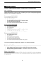
Front Panel
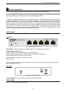
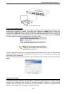
Figure 3 – DGS-1100-08 Front Panel
Power LED: The Power LED lights up when the Switch is connected to a power source.
Link/Act/Speed LED (Ports 1-8):
Flashing: Indicates a network link through the corresponding port.
Blinking: Indicates that the Switch is either sending or receiving data to the port.
Green: Indicates that the port is running at 1000M.
Amber: Indicates that the port is running at 10/100M.
Light off: No link.
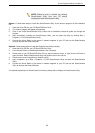
Reset: By pressing the Reset button for 5 seconds the Switch will change back to the default configuration
and all changes will be lost.
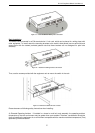
Rear Panel
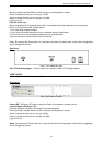
Figure 4 – DGS-1100-08 Rear Panel
5V/1A AC adapter: The port is where to connect the 5V/1A AC adapter.
DGS-1100-08P
8-Port 10/100/1000Mpbs PoE EasySmart Switch
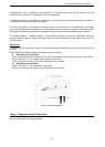
Front Panel
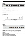
Figure 5 – DGS-1100-08P Front Panel
Power LED: The Power LED lights up when the Switch is connected to a power source.
PoE MAX. LED:
Light up: Indicates the power output to PDs is over 57W. No additional PDs can be powered for safety
consideration.
Blinking: Indicates if the user unplugged certain PDs and made the PoE power budget left over 7W, the PoE
MAX LED will blink 2 minutes.
Light off: Indicates the power budget is using less than 57W.
Link/Act/Speed LED (Ports 1-8):
Flashing: Indicates a network link through the corresponding port.