


MULTIFUNCTIONAL SETTINGS (continued)
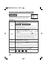
INPUT Menu
The three Input menu items listed in the table below can be manipulated. For
RGB input, the reception signal’s horizontal and vertical frequency is displayed
on the initial menu screen. Use the table below as a guide for operation.
4
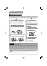
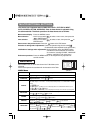
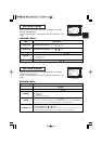
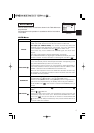
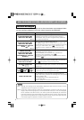
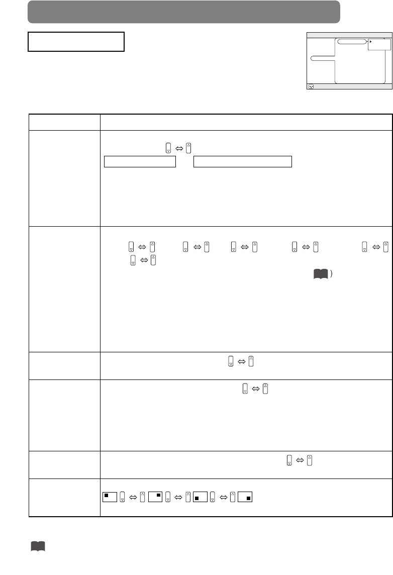
Example : INPUT Menu
(BNC)
MENU
: SELECT
MAIN
PICTURE-1
PICTURE-2
INPUT
AUTO
SCREEN
OPTION
WIRELESS
BNC
VIDEO
HDTV
SYNC ON G
P. IN P. INPUT
P. IN P. POSIT
RGB
COMPONENT
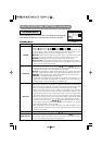
Item Description
BNC
BNC Pin (R/C
R
/P
R
, G/Y, B/C
B
/P
B
, H, V) function selection:
BNC (RGB)
BNC (COMPONENT)
(R) (G) (B) (H) (V) (C
R
/P
R
) (Y) (C
B
/P
B
) ( - ) ( - )
(Pins for RGB) (Pins for COMPONENT)
Selecting BNC (RGB) allows the 5 RGB2 pins (R/C
R
/P
R
, G/Y, B/C
B
/P
B
, H, V) to be
used as RGB signal BNC input as-is.
Selecting BNC (COMPONENT) allows the 3 leftmost RGB2 pins (R/C
R
/P
R
, G/Y,
B/C
B
/P
B
) to be used as the COMPONENT VIDEO input C
R
/P
R
, Y, and C
B
/P
B
pins.
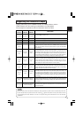
VIDEO
Select Mode of Signal Type (for VIDEO/S-VIDEO):
AUTO NTSC PAL SECAM NTSC4.43
M-PAL N-PAL
When AUTO is selected, the video/ S-video input function under ADJUST ( are enabled, and is
executed simultaneously so that the optimum signal mode is selected from among the modes listed above.
Use this function if the image becomes unstable with VIDEO/S-VIDEO. (e.g. The image becomes irregular, or lacks color.)
•
AUTO mode may not function correctly with a PAL60 signal and certain other signals.
• The AUTO mode operation requires approximately 10 seconds.
• For COMPONENT VIDEO, the signal type is identified automatically even if
this function is inactive. For a HDTV signal, refer to the item HDTV below.
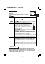
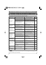
HDTV
Select HDTV Signal Mode: 1080i 1035i
•
If the selected HDTV mode is incompatible with the input signal, the picture may be distorted.
SYNC ON G
On/Off SYNC ON G Mode: TURN ON TURN OFF
Selecting TURN ON turns on the SYNC ON G mode. The SYNC ON G mode
allows reception of SYNC on G.
• In the SYNC ON G mode, the picture may be distorted with certain input
signals. In such a case, remove the signal connector so that no signal is
received and turn SYNC ON G off, and then reconnect the signal.
P. IN P. INPUT
P. IN P. screen (*) input signal selection: VIDEO S-VIDEO
Selects the signal displayed on the P. IN P. subscreen.
P. IN P. POSIT
P. IN P. screen (*) display position selection:
Selects the position at which the P. IN P. subscreen is displayed.
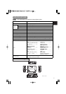
INPUT Menu
(*) The P. IN P. (picture-in-picture) function displays the video signal image in a subscreen (P. IN P. screen) on
top of the screen on which the RGB signal image is being displayed. (See “Displaying Child Window” Vol.1
.)
5
24