


Silicon Image, Inc.
Scan Plus v2 User Manual
10
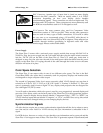
BNC Connectors: Another type of input that is found on many display
devices is the BNC connector. There are usually either 3, 4 or 5 BNC
connectors depending on how your display device handles
synchronization signals. These connectors are used on higher-end TVs,
monitors and CRT projectors. These connectors are most commonly used
for RGB but are sometimes used for Y-Pr-Pb signals as well.
RCA Connector: The most common plug used for Component Video
connections consists of 3 RCA-type jacks. These are the same connectors
that are used for many types of audio connections. VGA-to-RCA cables
are very rare so we recommend using a VGA-to-BNC cable (above) in
combination with a set of three BNC-to-RCA adapters. These adapters are
available through retailers specializing in high-end audio and video
equipment or from electronics supply houses such as Radio Shack.
Power Supply
The iScan Plus v2 comes with a universal power supply module that accepts 100–240 VAC at
50/60 Hz. Plug the power supply into the wall outlet and then plug the small round connector
into the “DC-In” jack on the back of the iScan Plus v2. There is a small gray ferrite that is
designed to snap over the wire near the end of the small power cable that leads from the power
supply to the iScan Plus v2. Looping the end of the cable through the ferrite twice in the same
direction will secure it in place.
Color Space Selection
The iScan Plus v2 can output video in one of two different color spaces. The first is the Red-
Green-Blue (RGB) color space that is commonly used for projectors, displays and monitors that
are designed to accept computer video output.
The second is Component Video, but is more accurately called Y-Pr-Pb though you may hear it
referred to as Y-Pb-Pr, YUV, Y-Cr-Cb or Y/B-Y/R-Y (read “Y, B minus Y, R minus Y”). This color
space is commonly used for newer digital TV sets, displays and projectors that are designed for
use with Digital TV (DTV) tuners.
You will need to determine which color space is used by your progressively scanned display and
move the Color Space switch on the back panel of the iScan Plus v2 to the appropriate position.
Typically, inputs on display devices that are labeled “Component Video”, “DTV” or “HDTV” are
Y-Pr-Pb whereas inputs that are labeled “Computer” or “VGA” are RGB. Once set up, this switch
should not need to be changed unless you are changing display devices.
Synchronization Signals
All video devices require one or more synchronization signals that tell the device when to start a
new line and/or a new field. For Y-Pr-Pb devices, this sync information is embedded in the Y
signal.
For RGB devices, there are a variety of ways that this sync information can be conveyed and the
iScan Plus v2 can support most of these. The iScan Plus v2 generates separate H (horizontal) and