


Silicon Image, Inc.
Scan Plus v2 User Manual
11
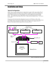
V (vertical) sync signals in addition to the RGB outputs. This results in a total of five signals
(RGB/HV). For many configurations, these five signals will be part of a single VGA VGA
output cable and there will be no need to worry about the individual signals. For some devices
you may need to connect all five of these signals to individual BNC or possibly RCA type
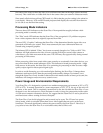
connectors. See Table 1 below for more specific connection info.
Some display devices require that the two H and V sync signals be combined into a single
“composite sync” signal, resulting in a total of 4 signals (RGB/S). Devices requiring composite
sync typically accept the three video signals as well as the composite sync signal on BNC type
connectors.
Other devices require that the composite sync signal be further combined with the RGB Green
signal. This is referred to as “sync on green” and is typically connected to the device using 3 BNC
connectors, though 3 RCAs may also be used.
If your output device falls into either of these last two categories – composite sync or sync on
green – the iScan Plus v2 will need to be internally configured to output the appropriate type of
sync signal. To do this you will need to follow the directions in Appendix A.
With Y-Pr-Pb connections, the composite sync is always combined with the Y signal. The iScan
Plus v2 will automatically do this whenever the color space switch is set to Y-Pr-Pb. It is not
required to configure any of the internal jumpers for any Y-Pr-Pb device.
Wire Color RGB/HV RGB/S(comp) Y-Pr-Pb Other
Red R (Red) R (Red) Pr Cr or R-y
Green G (Green) G (Green) Y Y
Blue B (Blue) B (Blue) Pb Cb or B-y
White (or
Gray)
H (Horizontal) C-Sync no connect no connect
Yellow (or
Black)
V (Vertical) no connect no connect no connect
Table 1: Wire Color Cross-Reference