


Silicon Image, Inc.
Scan Plus v2 User Manual
24
straddling the two pins labeled “NORMAL” which are nearest the front of the iScan board.
21) Remove this jumper from its current position by grabbing the top of the jumper and pulling
directly away from the PC board.
22) Push the jumper onto the two pins closest to the rear of the iScan board, labeled “C-SYNC.”
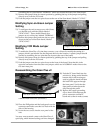
Modifying Sync-on-Green Jumper
Setting
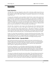
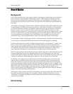
23) To configure the unit to merge sync with Green,
you should work with the jumper labeled
“SYNC-ON-G.” There should already be a
jumper on two of the pins, labeled “NORMAL.”
24) Remove this jumper and push onto the two pins
closest to the rear of the iScan board, labeled
“SYNC-ON-G.”
Modifying VCR Mode Jumper
Setting
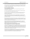
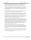
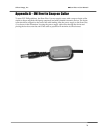
25) To enable the iScan Plus v2’s time base corrector, you will need to modify the setting of a
jumper which is not labeled. See the diagram above for the location. A plastic jumper should
already be straddling the two pins that are closest to the rear of the board.
26) Remove this jumper from its current position by grabbing the top of the jumper and pulling
directly away from the PC board.
27) Push the jumper onto the two pins closest to the front of the board. Note that this is the
opposite convention from the other two jumpers which are in NORMAL mode when on the
two rear-most pins.
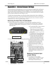
Reassembling the iScan Plus v2
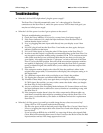
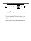
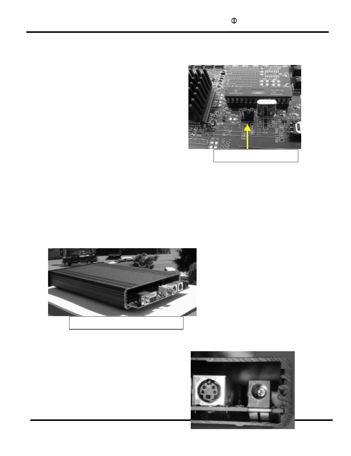
28) Push the PC board back into the
unit slowly, being careful that the
bottom slots in the housing are
used to guide the board and that
the front LEDs appear through
the front panel. Verify that the
front panel switches protrude
fully through the panel.
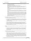
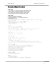
29) Replace the copper grounding
clip so that it tucks between the
power connector and the PC
board and so that it makes contact
with the metal enclosure. (See below).
30) Place the EMI gasket and the back panel over the
connectors and make sure that it is flush with the
sides of the housing.
31) Screw the two screws into the rear panel of the
unit.
You may want to attach a note to the iScan Plus v2
specifying which internal setting you have changed.
The iScan board sits in the bottom slot
Jumper is on NORMAL pins