


Silicon Image, Inc.
Scan Plus v2 User Manual
17
+RZLW:RUNV
Background
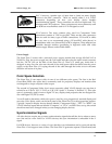
On a normal television, the video image is made by sweeping an electron beam across the face of
the set where it excites phosphors causing them to glow. While repeated scanning across the
tube, the television changes the intensity of the beam to vary the brightness of the image. If you
look closely at the picture on a television set, you will see the horizontal scan lines that make up
the image.
The standard video signal in North America (officially referred to as the NTSC standard) consists
of approximately 240 visible horizontal scan lines per video field, with fields occurring 60 times
per second. When this standard was originally conceived, the average television was relatively
small so a typical viewer would not be able to pick out the individual scan lines but would
instead see what appears to be a smooth picture. As televisions have grown larger however, these
lines have become more noticeable and with large televisions and projectors, they have become
an annoying element of the image. Video Line Doublers were originally conceived to try to
address this issue by increasing the number of lines scanned across the face of the display.
It is not simply a matter of drawing more lines. To understand how a modern line doubler works,
it is necessary to understand the difference between interlace and progressive scanning.
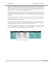
Interlace scanning is used in today’s standard analog televisions. An interlaced TV “paints” the
lines of a frame in two separate passes. Half of the lines are drawn in the first pass (the even
lines), and the other half (the odd lines) are drawn in the second pass. First devised so that early
TVs could have decent resolution with the limited transmission technologies available at the
time, interlaced scanning has several unfortunate side effects that are discussed below.
The first major problem with interlaced scanning is that the image may visibly flicker if the screen
is large enough that it represents a significant portion of the viewing angle. Even with small
screens, sharp edges on objects may flicker. This effect is due to the fact that only every other line
is drawn on each pass causing hard edges to appear to move up and down on each field.
In addition, more problems are caused by the fact that horizontal lines that are one above the
other are from two different fields, that is, they were not captured by the video camera at the
same time and they are not drawn on the screen at the same time. If motion occurs during the
time between these two fields, the edge of the moving object will appear to be very jagged. This
jagged edge is usually not noticeable to most television viewers because as the new field is being
drawn, the “older” field is fading in intensity. However, on high-resolution displays or on
devices such as Liquid Crystal Displays (LCD’s) or plasma panels that do not fade, an interlaced
image will contain noticeable motion artifacts.
These types of effects are the reason that a line doubler can’t simply repeat each of the incoming
lines and expect the output image to be acceptable. Instead a doubler will first have to fully
“deinterlace” the image, removing the motion artifacts described above while still retaining as
much detail as possible.
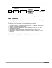
Deinterlacing