


UPS WITH BYPASS ELECTRICAL INSTALLATION
Eaton 9170
+
UPS (3–18 kVA) User's Guide S 164201393 Rev E www.eaton.com/powerquality
35
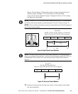
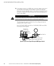
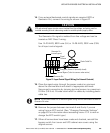
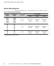
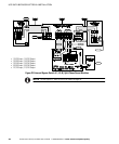
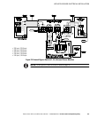
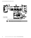
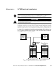
The following notes are referenced in the system wiring diagrams
(Figure 22 through Figure 24).
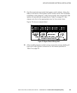
NOTE 1 The customer must provide input overcurrent protection. See NEC
Section 240-21 or local requirements. See Table 1 on page 21 for circuit breaker ratings to
size the protection device according to local code requirements.
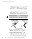
NOTE 2 The UPS bypass switch must be installed within sight of the UPS. To properly
install, complete the voltage and phase check procedure in “Startup for Hardwired Units” on
page 71. The wires coming from the side of the switch must be connected as described in
Step 13 on page 32.
NOTE 3
The customer must size the AC circuit conductors. All AC circuit
conductors, including the neutral conductor, must be the same size (ampacity), have the same
rating (75°C) copper wire, and be sized according to the input circuit breaker. See Table 2 on
page 22 for recommended wire sizes. The UPS input and output conductors must be run
through separate conduits.
NOTE 4
The customer must provide output overcurrent protection. See NEC
Section 240-21 or local requirements. See Table 16 and Table 17 on pages 98 and 101 for
maximum output overcurrent protection device ratings.
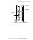
NOTE 5 See “Equipment Clearances” on page 9 for installation and service clearances
before installing the UPS. Use flexible conduit on the UPS or the external battery cabinet if
either must be moved.
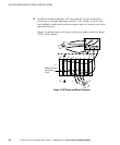
NOTE 6 External UPS battery cabinets are optional. See “Battery Cabinet Installation” on
page 61 for installation instructions.
NOTE 7 UPS output circuits shall be installed in dedicated conduit systems and not shared
with other electrical circuits.