UPS ELECTRICAL INSTALLATION
Eaton 9170
+
UPS (3–18 kVA) User's Guide S 164201393 Rev E www.eaton.com/powerquality
45
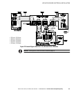
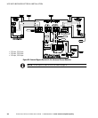
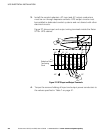
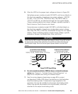
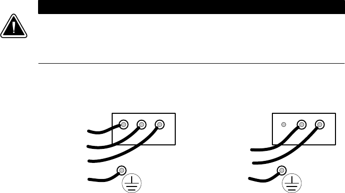
5. Wire the UPS for the proper input voltage as shown in Figure 28.
Split-phase power modules (model ASY-0673, with brown labels on
the front) are capable of supplying two output voltages: 100/100
for 200, 110/110 for 220, 120/120 for 240, 120/120 for 208, or
127/127 for 220 Vac, as selected through the front panel display.
These modules produce two output voltages, typically required in
North America, South America, and Japan.
Universal power modules (model ASY-0674, with black labels on
the front) are capable of supplying a single-phase output voltage:
200, 208, 220, 230, or 240 Vac, as selected through the front panel
display. These modules produce a single output voltage, typically
required in Europe, the Middle East, Asia, and Africa.
C A U T I O N
Confirm that the UPS is wired for the proper input voltage as shown in Figure 28, and that
the proper power modules (either split-phase or universal) are installed to produce the
desired output voltage. Do not mix the two types of power modules in the same UPS
cabinet.
(b) Universal Power Modules
(2-wire plus ground input)
200, 208, 220, 230, and 240 Vac
(a) Split-Phase Power Modules
(3-wire plus ground input) (2 PEN)
100/200, 110/220, 120/208, 120/240, 127/220 Vac
321321
L2
L1
N
GND
L1
L2/N
GND
Figure 28. UPS Input Wiring
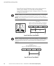
6. For units manufactured before 2009 that have an isolated transformer
option. See Chapter 5, “Isolated Output Wiring Diagrams” on
page 53 to complete the wiring for isolated output.
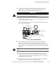
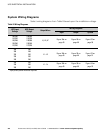
7. See the wiring diagrams beginning on page 48 for output
configurations. Make UPS output connections on the backplane
board terminating studs. Compression lugs (supplied in the
accessory kit) may be installed on the proper terminating studs.
Wires may also be terminated with ring terminals, which are
attached to the output terminating studs.


