


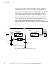
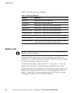
OPERATION
Eaton 9170
+
UPS (3–18 kVA) User's Guide S 164201393 Rev E www.eaton.com/powerquality
82
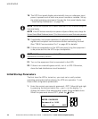
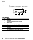
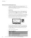
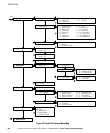
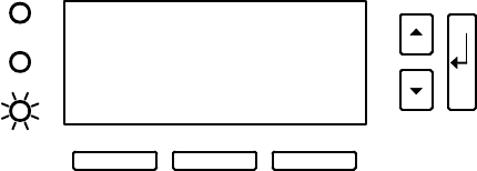
During normal operation, the display appears as shown in Figure 56:
Md: Current UPS operating mode
St: Operational state
Mn Number of power modules
Bn Number of battery module strings currently online
nn Total number of module slots in the cabinet
The count of battery strings does not include additional battery strings
contained in connected external battery cabinets.
Md: AUTO M4−B7−12
St: ON LINE
acvout 232 V
Config OFF Menu
Figure 56. Front Panel Display (Normal Operation)
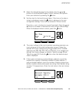
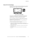
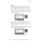
Operating parameters on the third line of the display vary depending on
the operating mode. Use the
B
and
Y
buttons to scroll through the
available parameters. After five seconds of inactivity, the system
automatically saves the parameter that was selected as the default
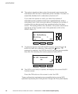
display parameter. The parameters available for display are:
S Phase 1 Input Voltage
S Phase 2 Input Voltage
S Phase 1 Output Voltage
S Phase 2 Output Voltage
S Total System Percent Load
S Phase 1 Percent Load
S Phase 2 Percent Load
S Battery Voltage
S Estimated Battery Runtime