m) Retighten the jam nuts (30) and repeat
Steps “f”,
“g”
and
“h”.
n)
Repeat this procedure as necessary to ob-
tain the desired stopping position.
2.3.2 Long Operation:
This feature is provided so an adjustment can
be made to extend the LS4 open time and
accommodate presses with long strokes and/or
slow crankshaft speeds.
a)
b)
c)
d)
e)
f)
g)
Turn electrical power off to main control
panel.
Remove end cap (31) from timer by remov-
ing the two socket head cap screws.
Remove jam nuts (30) and washer (40).
Remove adjusting knob (29).
Note that cam No. 5 (33A) has four dowel
holes for adjustment. Cams are factory
adjusted to a minimum setting of
135”.
Rotate cam No. 5 (33A) to increase or
decrease cam dwell.
Insert the dowel of the adjusting knob
through cam No. 5 (33A), cam No. 4 (33)
and spacer (41) to engage cam No. 3 insert
(28). Proper engagement can be determined
by rotating the cam adjusting knob. All
cams, except cam No. 3 (28A), will turn as
a unit when the knob is rotated.
Adjust top stop position and brake monitor-
ing cam as outlined in Paragraph 2.3.1.
2.3.3 Timer Synchronizing Instructions:
a)
First, refer to Paragraph 2.3, Timer Ad-
justments. Where two
Airflex@
timers
exist, this section applies to both units.
b)
Set stroking selector on control panel to
“inch”, turn power “ON”, and inch press
3.0 Maintenance
n
!
Danger:
Prior to performing any maintenance, repair or
adjustment on the
Airflex@
Timing Rotorseal
and Cam Limit Switch, make sure that the ma-
chinery will remain secured in a safe manner.
Failure to do so could result in serious injury
or possibly death.
n
!
Warning:
Only qualified maintenance personnel should
install, adjust or repair these devices. Faulty
workmanship will result in unreasonable ex-
posure to hazardous conditions, injury or
severe damage to the equipment.
3.1
7
c)
d)
e)
f)
g)
h)
i)
j)
to top of stoke. With electrical power
“OFF”, remove both timer end caps.
Make
sure
the machinery is secured in a safe
manner.
On each timer, loosen the locknuts
(30)
and rotate the cam assemblies,, so that
the leading edge of the lobe on both cam
No. 4 and 5 (33 and 33A) just start to open
the LS4 breaker points. Tighten locknuts
(30). Also, refer to brake monitoring cam
adjustment at this point, when applicable
(see Paragraph 2.3.1 and Figure 4).
Set the control panel stroking selector to.
‘Single Stroke”, operate the press, and
observe the stopping position. Retard or
advance both cam assemblies, as required,
to establish desired top stop position.
Tighten locknuts.
With “top stop” established, it is likely at
this stage of adjustment that one cam’
No. 4 of one timer may slightly lead the
cam No. 4 of the second timer.
Inch the press through the stroke just far
enough for the lobe of the
leading cam
to
barely contact the fiber cam follower on
the breaker point.
With power “OFF”,
adjust the second
cam assembly to an identical setting.
Tighten locknuts.
Run the press again on “Single Stroke” a
few times to verify proper operation and
stopping position.
With power “OFF”,
replace the felt seal
(34), the timer end caps and socket
screws.
The two timers should now be properly
synchronized, and the press ready for
operation.
n
!
Caution:
Before you begin any work, study this manual
so that you completely understand what is
required. Do not risk injury. Follow the
instructions.
Breaker Point Assemblies:
The breaker points furnished with the
Airflex@
timers have silver alloy contacts.
Standard automotive breaker points have
tungsten contacts and
must not
be used as a
substitute. The breaker points should be
checked periodically for wear.
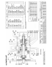
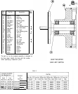
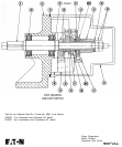
Refer to Figure 6 when making any adjustments.


