


1
1-6
EMC Fibre Channel Storage-System Configuration Planning
About Fibre Channel Storage Systems and Networks (SANs)
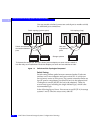
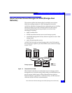
You can cascade switches (connect one switch port to another switch)
for additional port connections.
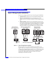
Figure 1-3 Switch and Hub Topologies Compared
Switch Zoning
Switch zoning defines paths between connected nodes. Each zone
encloses one or more adapters and one or more SPs. A switch can
have as many zones as it has ports. The current connection limits are
four SP ports to one adapter port (the SPs fan in to the adapter) and
15 adapters to one SP (the SPs fan out to the adapters). There are
several zone types, including the single-initiator type, which is the
recommended type.
In the following figure, Server 1 has access to one SP (SP A) in storage
systems 1 and 2; it has no access to any other SP.
S
witch uses discrete
c
onnections between
p
orts
SP SP
Server Server
Adapter
Storage systems
Adapter
Server
SP
Adapter
Switch topology (point-to-point)
Hub uses
loop between
ports
SP
Server
Server
Adapter
Adapter
Server
Adapter
Hub topology (loop)
T
o illustrate the comparison, this figure shows just one adapter per server and one switch or
hub. Normally, such installations include two adapters per server and two switches or hubs.