Installation
13
2.5.4 Special Considerations for Parallel Systems
1. Consider the grounding configuration of the UPS system before finalizing module placement. For
optimal ground performance, the Liebert
®
APM
™
modules should be close together. See 3.2.5 -
Cabling Guidelines.
2. For optimal load-sharing performance, the UPS bypass input cables and output cables should be
approximately the same length, plus or minus 20 percent.
3. Position modules in such a way as to minimize the length of power cables and control wiring
between UPS modules and the paralleling cabinet.
2.5.5 Special Considerations for 1+N Parallel Systems
Consider the grounding configuration of the UPS system before finalizing module placement. See
3.2.5 - Cabling Guidelines.
Emerson recommends matching the impedance in the bypass path of paralleled systems as closely as
possible.
The impedance mismatch can be minimized by controlling the wiring length of each unit. The design
and the layout of the UPS system and associated panels and cabling should be examined closely to
ensure that cable lengths and impedances are closely matched. The Liebert 1+N UPS module is
supplied with a sharing reactor to minimize the impact of cable impedance mismatch. The cabling
impedance must be carefully controlled to ensure good bypass current sharing.
For Liebert APM
™
systems, the cabling impedances must be within 10% from maximum to minimum.
If the cabling impedances must be greater than 10%, contact your Emerson representative to
calculate whether the system will result in an overload condition when operating on bypass.
When bringing the 1+N system online for the first time or after removing one unit, Emerson
recommends checking the bypass current mismatch. To check the bypass current mismatch:
1. Place a load on the bypass of each UPS module.
2. View the output current of each unit.
The accuracy of the currents displayed on the UPS module is sufficient for this check. If the mismatch
is greater than 10%, the bypass impedances must be balanced or the load must be limited to less than
the maximum rating.
2.6 45kVA and 90kVA UPS Frames—Auxiliary Cabinets
The 45kVA frame consists of a single cabinet housing the UPS components and the internal battery
string. The 90kVA frame, also a single cabinet, does not accommodate internal batteries, but does
provide for an internal 4-breaker bypass, or an internal transformer. The internal transformers are
available with either 480V:208V or 600V:208V input primaries.
Optional battery cabinets are available for each Liebert
®
APM
™
model to provide extended run time.
Each battery cabinet houses a single string of batteries per cabinet that operate in parallel with the
Liebert APM’s internal batteries (45kVA frame only). The battery cabinets are designed to be bolted
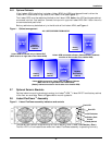
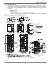
to the left side of the UPS (see Figure 1). Refer to 4.4 - External Battery Cabinet Installation for
details.
Optional Liebert BDC
™
units are available. These cabinets house the components necessary to
provide an external wraparound maintenance bypass switch for servicing the UPS.
Liebert BDCs are designed to be bolted to the right side of the UPS (see Figure 1). Refer to 5.3 -
Locating the Cabinet for further details.
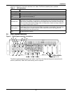
System Composition
A UPS system can comprise a number of equipment cabinets, depending on the system design
requirements—e.g., UPS cabinet, External Battery Cabinet and External Bypass Cabinet. In general,
all cabinets used will be the same height and are designed to be positioned side-by-side to form an
aesthetically appealing equipment suite.


