


Electrical Connections—UPS
34
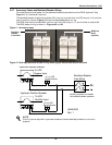
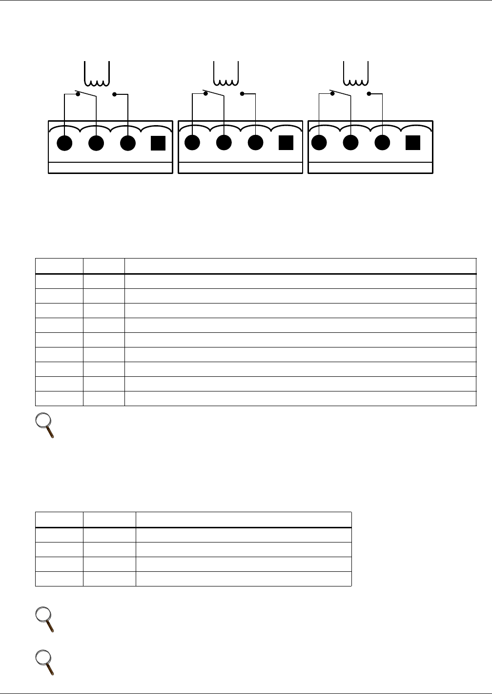
3.4.2 Output Dry Contacts
The Auxiliary Terminal Block has three output dry contact relays (see Figure 18 and Table 6).
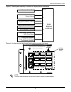
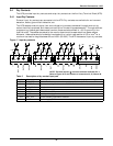
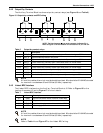
Figure 18 Output dry contacts and EPO wiring
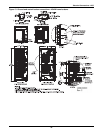
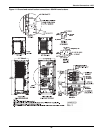
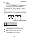
3.4.3 Liebert BDC Interface
The Liebert BDC interface is on the Auxiliary Terminal Block at J5. Refer to Figure 16 for the
location of connector J5 and to Figure 17 for circuit details.
Table 6 Output dry contact relays
Position Name
Description
J11.2 BFP_O Bypass feedback protection relay. Normally open. Closed when bypass SCR is shorted.
J11.3 BFP_S Bypass feedback protection relay center
J11.4 BFP_C Bypass feedback protection relay. Normally closed. Open when bypass SCR is shorted.
J12.2 INV_O Inverter mode relay. Normally open. Closed when UPS is in inverter mode.
J12.3 INV_S Inverter mode relay common
J12.4 INV_C Inverter mode relay. Normally closed. Open when UPS is in inverter mode.
J10.2 MFP_O Main feedback protection relay. Normally open. Closed when bypass SCR is shorted.
J10.3 MFP_S Main feedback protection relay common
J10.4 MFP_C Main feedback protection relay. Normally closed. Open when bypass SCR is shorted.
NOTE
All auxiliary cables of terminal must be double-insulated. Wire should be 20-16AWG stranded
for maximum runs between 80 and 200 feet (25-60m), respectively.
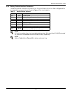
Table 7 Liebert BDC interface
Position Name
Description
J5.1 Q3BP Input circuit breaker status of external Liebert BDC
J5.2 Q2BP Output circuit breaker status of external Liebert BDC
J5.3 EXT_OUT Input circuit breaker status of internal Liebert BDC
J5.4 GND Power supply GND
These contacts cannot be active unless they are set via software.
NOTE
All auxiliary cables of terminal must be double-insulated. Wire should be 20-16AWG stranded
for maximum runs between 80 and 200 feet (25-60m), respectively.
NOTE
Refer to Table 11 and Figure 27 for the Liebert BDC wiring.
J10
MFP_O
MFP_S
MFP_C
J12
INV_C
INV_S
INV_O
J11
BFP_C
BFP_S
BFP_O
NOTE: The black square () on each connector indicates Pin 1.
Refer to Figure 16 for the location of connectors J10, J11 and J12.