


Chapter 3 Electrical Installation 17
HIPULSE U UPS Single Module And “1+N” (Expandable) 160/200/300/400kVA User Manual
The presence of a radio frequency interference (RFI) suppression filter inside the UPS determines a residual earth
current greater than 3.5mA and less than 1000mA.
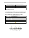
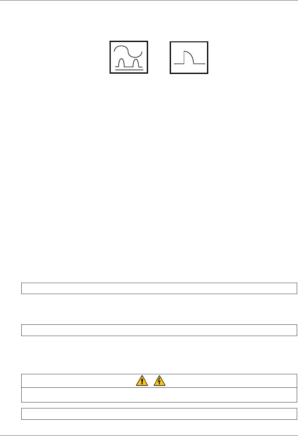
Residual current circuit breakers (RCCBs) must be sensitive to DC unidirectional pulse (Class A) in the network and
insensitive to transient current pulses. They are identified by the symbols respectively:
Figure 3-1 Symbols of residual current circuit breaker (RCCB)
These isolators must have an average sensitivity, possible adjustable between 0.3A and 1A.
It is recommended that the selectivity with every RCD be verified both upstream of the input distribution board and
downstream (towards the load).
UPS battery
The UPS Battery is protected by means of a control circuit that operates the tripping mechanism of an automatic
circuit breaking device (having a variable trip setting). The tripping mechanism using an undervoltage release coil that
operates on a present minimum voltage level.
The circuit breaker is essential for maintenance of the battery and is normally located near to the battery installation.
Output of the system
In the eventuality that an external distribution panel is used for load distribution, the selection of protective device
must provide discrimination with those that are use at the input to the UPS module.
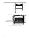
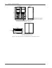
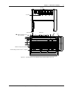
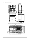
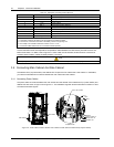
3.1.7 Cabling Procedure
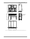
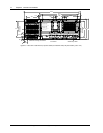
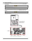
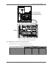
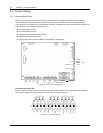
Once the equipment has been finally positioned and secured, refer to Figure 3-2 and Figure 3-3 to connect the power
cables as described in the following procedures:
1. Verify that the UPS equipment is totally isolated from its external power source and all the UPS power isolators are
open. Check that these supplies are electrically isolated, and post any necessary warning signs to prevent their
inadvertent operation.
2. Open the UPS door and remove the lower protective cover to gain access to the connections bars.
3. Connect the safety earth and any necessary bonding earth cables to the copper earth busbar located on the floor
of the equipment below the power connections.
Note: The earthing and neutral bonding arrangement must be in accordance with local and national codes practice.
Common Input Connections
4. For common bypass and rectifier inputs, connect the AC input supply cables between the mains distribution panel
and the UPS input supply busbars (U1-V1-W1-N1 terminals) and tighten the connections to 13 Nm (M8 bolt), and to
26 Nm (M10 bolts). ENSURE CORRECT PHASE ROTATION.
Split Bypass Connections
5. If a split bypass configuration is used, connect the AC input supply cables to the input busbars (U1-V1-W1
terminals) and the bypass AC supply cables to the bypass busbars (U2-V2-W2-N2 terminals) and tighten the
connections to 13 Nm (M8 bolt), to 26 Nm (M10 bolt), and to 50 Nm (M12 bolt). ENSURE CORRECT PHASE
ROTATION.
Warning
Ensure that any links (
*
) fitted between rectifier input and bypass busbars are removed. But do not remove those between the
neutral terminals. See Figure 3-2 and Figure 3-3.
Output System Connections