


Appendix 1 Transportation Restraints Removing Procedures 65
HIPULSE U UPS Single Module And “1+N” (Expandable) 160/200/300/400kVA User Manual
5. Reinstall the installation hole cover and the lower switch baffle plate with the screws removed in step 1. You might
as well install the lower switch baffle plate after UPS commissioning.
6. Reinstall the back panel of the cabinet with the screws removed in step 2. You can also carry out this step after
UPS commissioning.
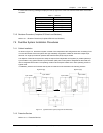
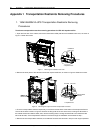
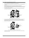
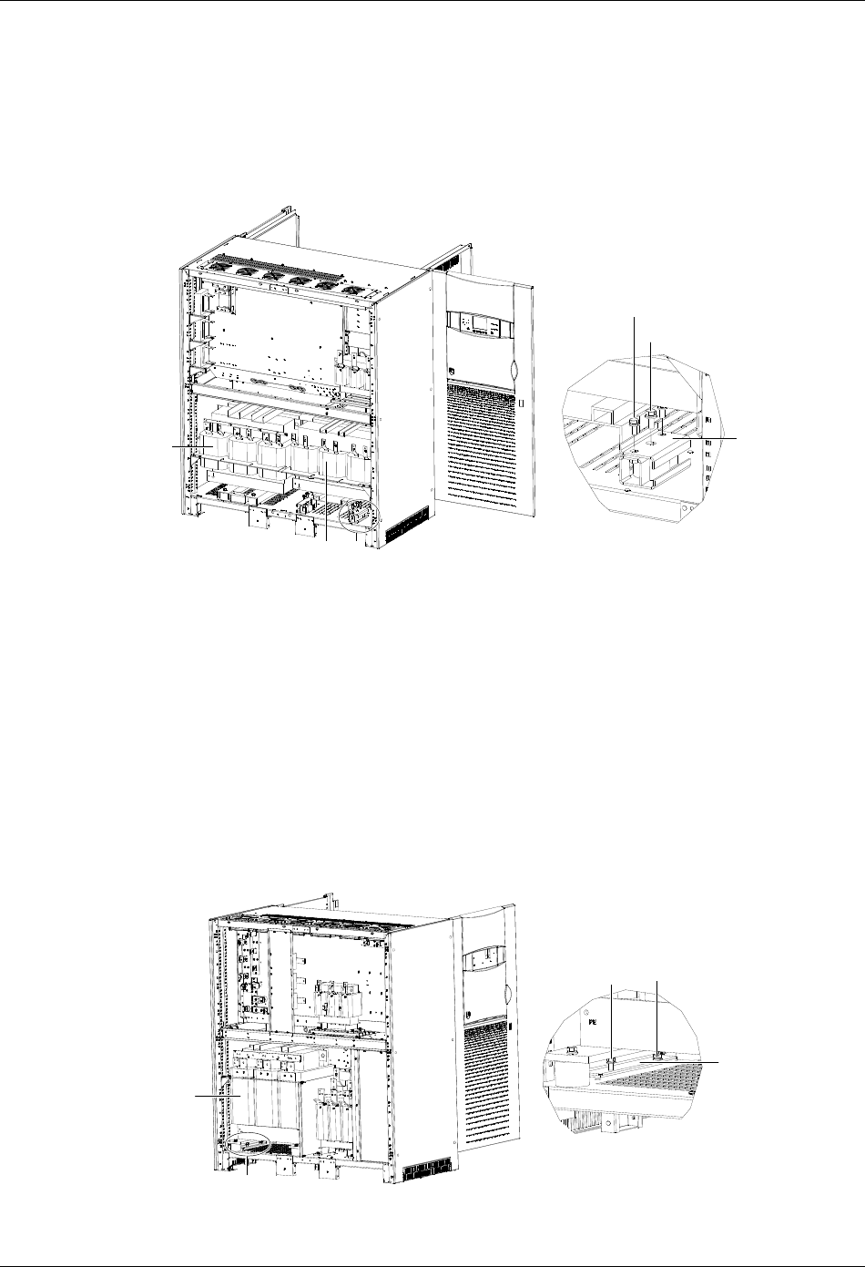
Transformer transportation restraints removing procedures for UPS with 12-pulse rectifier
1. Repeat the preceding steps 1 through 4 to remove the transportation restraints of the output transformer (see
Figure 3).
M12螺栓
M10螺栓
A 放大处图
出器输变压
固定件
A移相 器变压
A
A amplified view
Output
transformer
Phase-shifting
transformer
M10 bolt
M12 bolt
Transportation
restraint
Figure 3 Removing the transformer transportation restraints
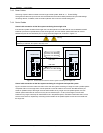
2. Remove the transportation restraints of the phase-shifting transformer.
There are two transportation restraints respectively in the front and at the back, totally four, at the bottom of the
phase-shifting transformer. Remove the two M10 bots at both sides and one M12 bolt in the middle of each
transportation restraint, as shown in Figure 3. Remove the four transportation restraints, and then reinstall the four
M12 bolts in their original positions.
3. Repeat the preceding steps 5 and 6.
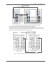
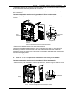
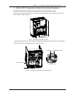
2. 300kVA UPS Transportation Restraints Removing Procedures
Transformer transportation restraints removing procedures for UPS with 6-pulse rectifier
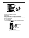
1. Remove the back panel of the cabinet to reveal the output transformer, as shown in Figure 4. Retain the screws.
A 放大处图
出器输变压
固定件
M10螺栓
A
A
A amplified view
Output
transformer
M10 bolts
Transportation
restraint
Figure 4 Removing the output transformer transportation restraints