


Chapter 5 Operating Instructions 43
HIPULSE U UPS Single Module And “1+N” (Expandable) 160/200/300/400kVA User Manual
3. Wait until the test completes.
After five seconds, a pop window will appear to showing the result of this diagnosis: rectifier, inverter, monitor OK or
fault.
4. Stop the test.
If required, the test may be stopped before completion by selecting Stop testing on the Command menu.
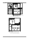
5.6 Maintenance Bypass Procedure (And UPS Shut Down)
The following procedure transfers the load supply from being protected by the UPS into being connected directly to
the AC input bypass supply though a maintenance bypass switch.
Caution – risk of load interruption
Except in emergency situations, so as not to risk a short interruption in powering the load, before initiating this bypass procedure,
confirm that no warning status is displayed in the top right corner of the LCD screen.
If a warning status is displayed, the operator will be prompted to confirm or cancel any action that can lead to load interruption.
1. Press the INVERTER OFF button on the operator control and display panel.
The UPS inverter will shut down and the load is supplied through the static bypass supply. At this point, the inverter
LED extinguishes, and the alarm LED turns on.
2. Close the maintenance bypass switch Q3.
The maintenance bypass supply is now in parallel with the UPS static switch supply, and the LCD shows messages
reflecting the actions taken (that is, maintenance bypass closed, etc.).
3. Open the output switch Q5.
This ends the bypass procedure. The load is now powered directly from the maintenance bypass supply.
Note
The load equipment is not protected from AC supply aberration.
Proceed with following steps if rectifier and battery shutdown is also required.
4. Press and hold the emergency power off (EPO) button on the UPS door for two seconds.
This will disable further rectifier, inverter, static switch and battery operation, but will not affect the maintenance
bypass switch.
Note
Before carrying out this step, verify that the EPO contact is not connected to any external switch or device.
5. Open the input switch Q1 and the bypass switch Q2.
6. Open the BCB, which is located in the BCB box.
All LED indications and messages on the operator control and display panel will extinguish as the mains driven
internal power supplies decay.
The load is now powered from the maintenance bypass supply and the UPS is completely shut down.
5.7 Shutdown Procedure (Complete UPS And Load Shutdown)
This procedure must be followed to completely power down the UPS and load. All power switches, isolators and
circuit breakers will be opened and power will be removed from the load.
Caution
The following procedure will switch off all power to the load equipment.