


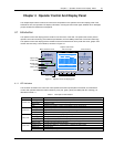
32 Chapter 4 Operator Control And Display Panel
HIPULSE U UPS Single Module And “1+N” (Expandable) 160/200/300/400kVA User Manual
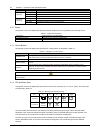
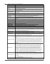
Current record window
Keeps a log of current alarms, ignores transient conditions that have been resolved. Use F1, F2 and F3 to read the
alarm messages.
For a complete history log, refer to the Records menu in Table 4-6.
Refer to Table 4-8 for a complete list of UPS alarm messages.
Keypad window
The function of menu keys F1 to F4 and HELP is shown by a self-explanatory icon as appropriate for the particular
window.
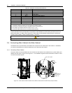
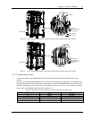
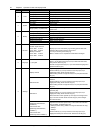
4.1.6 EPO Button
As shown in Figure 4-3, the UPS door provides an emergency power off (EPO) button. It is housed beneath a safety
cover to prevent inadvertent operation. After the EPO button has been pressed and hold for 2 seconds, it disables the
static switch block entirely (so removing load power). It also disables the rectifier and inverter, and trips the battery
circuit breaker. Under normal circumstances it does not remove UPS input power since this is applied through a
manually controlled external isolator; however, if the UPS input supply is connected through circuit breaker having an
electrical trip facility, the EPO switch can be used to drive the external circuit breaker’s trip circuit so as to remove the
UPS input power.
Emergency
power off (EPO)
button
Figure 4-3 Emergency power off button
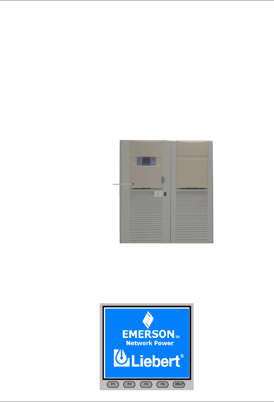
4.2 LCD Screen Types
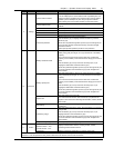
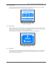
4.2.1 Start Screen
Upon UPS start, the UPS executes system test, and the start screen will appear and remains approximately 15
seconds, as shown in Figure 4-4.
Figure 4-4 Start screen