


TESTING & SERVICE
(continued)
2 --- 2
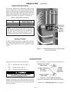
MANUAL LOAD TRANSFER
This procedure will manually transfer the load if the
controller is disconnected.
Do not manually operate the transfer switch
until both power sources are disconnected
(all conductors deenergized).
!
1. Deenergize both the normal and emergency source
conductors (remove fuses or open circuit breakers).
2. Use the m aintenance handle to manually operate the
transfer switch to the opposite source. F irst open the
closed contacts, then close the other contacts. Do no
t
leave both closed
.SeeManual Opera tion on page 1–3.
3. Thenremove
themaintenancehandle. See page1–3.
Verify that the maintenance handle
has b een removed before proceeding!
!
4. If the transfer switch is in the Emergency positi on
manually start the engine generator and then install
emergencysourcefuseorclosethecircuitbreaker.
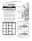
TROUBLE-SHOOTING
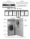
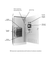
Note any optional accessories that may be furnished on
the ACTS and review their operation. Refer to any
separatedrawingsand/orinstructionsthatmaybepacked
with the ACTS.
Hazardous voltage capable of causing shock,
burns, or death is used in this switch.
Do not touch the power or load terminals
of the transfer switch!
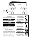
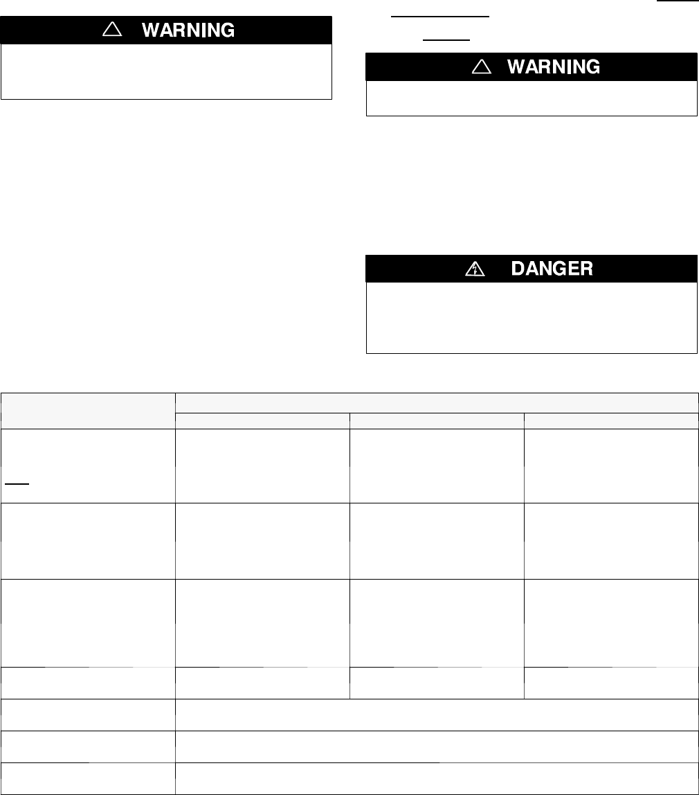
Table 2-1. Trouble-Shooting Checks.
P
R
O
B
L
E
M
CHECK IN NUMERICAL SEQUENCE
P
R
O
B
L
E
M
1OPERATION 2 GEN-SET 3VOLTAGE
Engine–generator set does
not start when the Transfer
Control switch is turned and
held
in Transfer Test position
or when normal source fails.
Hold Transfer Test switch 15
seconds or the outage must
be long enough to allow for
Feature1Ctimedelayplus
engine cranking and star ting.
Starting control must be in the
automatic position. Batteries
must be charged and
connec ted. Check wiring to
engine starting contacts.
---
Transfer switch does not
transfer the load to the
emergency source after the
engine–generator set starts.
W ait for Feature 2B time delay
to time out.
Generator output circuit
breaker must be closed.
Generator frequency must be
at least 95% of nominal (57 Hz
for a 60 Hz system.) *
Voltmeter should read at least
90% of nominal phase to
phase voltage between
terminals EA and EC (or EL1
and EL2 for 2 po le switches)*
Transfer switch does not
transfer the load to normal
source when normal returns
or when the Transfer Control
switch is released.
W ait for Feature 3A time delay
to time out.
---
Voltmeter should read at l east
90% of nominal phase to
phase voltage between
terminals NB and NC, NC and
NA , and NA and NB (or NL1
and NL2 for 2 po le switches).
Gen. does not stop after load
retransfer to normal source.
W ait for Feature 2E time delay
to time out.
Starting control must be in the
automatic position.
---
Failure to Synchronize
light comes on.
Conditions of Normal or Emergency Sources not suitable for closed transition transfer.
Recheck voltage and frequency of both sources. Press Alarm Reset pushbutton.
Extended Parallel Time
light comes on.
CN and CE contacts are closed longer than setting in the Control Panel. Open the discon-
nected source circuit breaker, then call your nearest ASCO Service Center for assistance.
TS Locked Out
light comes on.
Transfer lockout operation has occured; transfer switch is disabled from automatic operation.
Open the disconnected source circuit breaker, then call your nearest ASI for assistance.
* These are factory settings. Refer to Group 5 Controller User’s Guide.
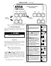
If the problem is isolated to circuits on the controller or the transfer switch, call your local ASCO Power Technologies
sales office or ASI. In the United States, call 1–800–800–2726. In Canada, call 1–888–234–2726. Furnish the Serial No.
and Catalog No. from the transfer switch nameplate.