


SECTION 2 TESTING & SERVICE
2 --- 1
TRANSFER TEST
Operate the 7000 Series ACTS at least once a month by
following the five–step Electrical Operation Transfer
Test procedure on page 1–5.
PREVENTIVE MAINTENANCE
Reasonable care in preventive maintenance will i nsure
high reliability and long life for the 7000 Series ACTS.
An annual preventive maintenance program is recom-
mended.
In the United States, ASCO Services, Inc. (ASI) is
ASCO Power Technologies’s national service
organization. ASI can be contacted at
1-800-800-2726 (ASCO) for information on
preventive maintenance agreements.
In Canada, for service call 1-888-234-2726 (ASCO).
Checklist f or Yearly Inspection
Hazardous voltage capable of causing shock,
burns, or death is used in this transfer switch.
Deenergize both Normal – Emergency power
sources before performing inspections!
❐ Clean the ACTS enclosure. Brush and vacuum
away any excessive dust accumulation. Remove any
moisture with a clean cloth.
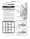
❐ Check the transfer switch contacts.Removethe
transfer switch barriers and check contact condition.
Replace the contacts if they become pitted or worn
excessively. Reinstall the barriers carefully.
❐ Maintain transfer switch lubrication.Ifthe
transfer switch is sub j ec ted to sever e dust or
abnor m al op er ating cond itions, ren ew f ac tory
lubrication on all mo vements and linkages.
Relub r ic ate the solenoid o per ato r if th e T S c o il is
replaced. Do not use oil; order lubrication kit 75-100.
❐ Check all cable connections & retighten them.
REPLACEMENT PA RTS
Replacement parts are available in kit form. When or-
dering parts provide the Serial No., Bill of Material No.
(BOM), and Catalog No. from the transfer switchname-
plate. Contact your local ASCO Power Technologies
Sales Office or ASI:
in United States call 1 800 – 800 – ASCO (2726)
or in Canada call 1 888 – 234 – ASCO (2726)
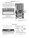
DISCONNECTING T HE CONTROLLER
The harness disconnect plugs are furnished for repair
purposes only and should not have to be unplugged. If
the controller must be isolated, follow these steps:
Disconnecting the Plugs
Do not unplug the controller
until steps 1a o r 1b is co m pleted.
!
1. Observe the position of the transfer switch.
a. If the trans fer s w itch is in the Normal position, first
place standby engine starting control in the off
position. Second, then open the emerg ency source
circuit b reaker. Third, open the normal source
circuit breaker.
b. Ifthe transferswitchis in the Emergency position,
first open the normal source circuit breaker. Sec-
ond, place t he engine starting control in the test
orru n position. Third, open the emergency sourc e
circuit breaker.
2. Separate the two quick disconnect plugs by squeez-
ing the latches. Do not pull on the harness wires.
Reconnecting the Plugs
Do not reconnect the controller
until steps 1a o r 1b is co m pleted.
!
1. Observe the position of the transfer switch.
a. If the transfer switch is in the Normal position,
firstbesurethatboth
normal and emergency
source circuit breakers areopen. Second, be sure
that the standby engine starting control is still in
the off position.
b. If the tran sfer switch is in the Emergency position,
firstbesurethatboth
normal and emergency
source circuit breakers are open.
2. The t wo harness plugs and sockets are keyed. Care-
fully align the plugs with the sockets and press
straight in until both latches click. Close t he door
!
3. Restore the two sources in sequence as follows:
a. If the transfer switch is in the Normal position,
first close the normal source circuit breaker.
Second, close the emergencysource circuit break-
er. Third, place the standby engine starting
control i n the automatic position.
b. Ifthe transferswitchis in the Emergency position,
first close the emergency source circuit breaker.
Second close the normal source circuit breaker.