


INDEX
Printed in U.S.A. Copyright --- ASCO Power Technologies 2006
A
alarm reset, 1–5, 2–2
auxiliary circuits, 1–2
C
cable
lugs, 1–2
preparation, 1–2
catalog number, inside cover
cleaning, 2–1
closed transition bypass, 1–5, 2–2
connections
line, 1–1
contact position indicators, 1–3
controller, 1–1
disconnecting, 2–1
see Controller User’s Guide
E
electrical operation, 1–5
emergency source accepted light,
1–4
extended parallel time, 2---2
F
f ai lu re to s yn ch ro ni z e, 2 --- 2
frequency, generator, 2–2
functional test , 1–2, 1–3, 1–4, 1–5
G
ground, controller, 1–1
H
harness, 1–1
disconnect plugs, 2–1
I
inspection, 2–1
installation, 1–1
indicators, contact position, 1–3
L
labels,
engine start contacts, 1–2
rating, cover
lights, 1–4, 1–5
lubrication, 2–1
M
maintenance handle, 1–3
maintenance, preventive, 2–1
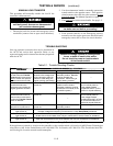
manual load transfer, 2–2
warning, 2–2
manual operation, 1–3
illustration of, 1–3
warning, 1–3
N
nameplate, cover
normal source accepted light, 1–4
O
operation
electrical, 1–5
manual, 1–3
illustration of, 1–3
warning, 1–3
optional accessories
see Controller User’s Guide
P
parts, 2–1
phase rotation check, 1–4
problem, 2–2
R
rating label, cover
replacement parts, 2–1
S
settings
see Controller User’s Guide
T
test, functional, 1–2, 1–3, 1–4, 1–5
time delays, 2–1
see Controller User’s Guide
Transfer Control selector switch
Retransfer Delay Bypass, 1–5
Transfer Test, 1–5
Transfer Switch Connected To
Emergency light, 1–5, 2–1
Transfer Switch Connected To
Normal light, 1–4, 2–1
transfer test, 1–5
transfer to emergency, 1–5
transfer to normal, 1–5, 2–1
trouble–shooting, 2–2
T S lo ck ed out , 2 --- 2
V
voltage checks, 1–4
voltage, pickup and dropout settings
see Controller User’s Guide