


INSTALLATION (continued)
1 --- 2
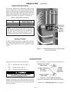
Engine Starting Contacts
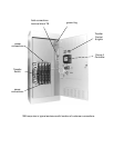
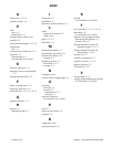
All customer connections, including the engine control
contact connections, are located on terminal block TB
which is mounted on the top right side of the enclosure.
Refer to the wiring diagram provided with the automatic
transfer switch and connect the engine start wires to the
appropriate terminals. See Figure 1–1 and Table A.
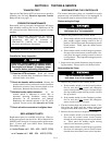
Table A. Engine start connections.
When normal source
fails
Terminals on
Terminal Block TB
contact closes TB1 and TB2
contact opens TB1 and TB3
Note: To temporarily disable engine control from
the automatic transfer switch you can unplug J3
from the small P3 receptacle at the bottom of the
assembly. BesuretoreconnectplugJ3totheP3
receptacle for automatic transfer switch operation.
Auxiliary Circuits
Connect auxiliary circuit wires to appropriate terminals
on transfer switch terminal block TB as shown on the
wiring diagram provided with this automatic transfer
switch.
engine start
connections
on
customer
terminal
block TB
Figure 1-1. Customer terminal block on the top right
side of the enclosure.
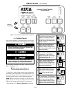
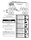
Functional Test
The Functional Test consists of three checks:
❐ 1 — Manual Operation Test, page 1–3
❐ 2—VoltageChecks,page1–4
❐ 3 — Electrical Operation, page 1–5
Do these checks in the order presented
to avoid damaging the ACTS.
!
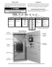
Read all instructions on the Wiring Diagram and labels
affixedto theautomatictransferswitch. Notethecontrol
features that are provided and review their operation
before proceeding.
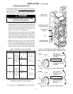
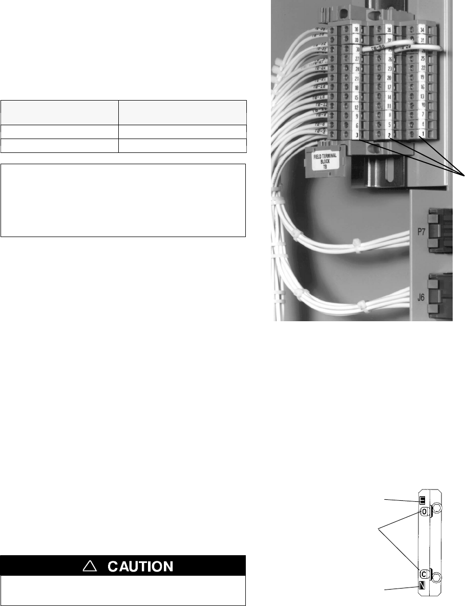
Note the position of the contact shafts as shown below.
window indicators
O is open
C is closed
Emergency contacts
(upper shaft)
Normal contacts
(lower shaft)
contact
position
indicators
(right side)
Figure 1-2. Contact position indicators.
Shown with Emergency open and Normal closed.
Continue to 1–ManualOperationTest on next page.