


TESTING & SERVICE
(continued)
2 --- 2
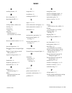
TROUBLE-SHOOTING
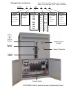
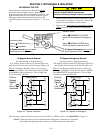
Note any opt ional accessories that may be furnished on
the ATB and review their operation. Refer to any
separate drawings and/or instructions that may be
packed with the ATB.
Hazardous voltage capable of causing
shock, burns, or death is used in this switch.
Do not touch the power or load terminals
ofthebypassswitchortransferswitch!
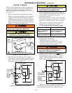
Table 2-1. Trouble-Shooting Checks.
CHECK IN NUMERICAL SEQUENCE
PROBLEM
1
OPERATION
2
GEN-SET
3
VOLTAGE
Engine–generator set does
not start when the Transfer
Control switch is turned and
held
in Transfer Test position
or when normal source fails.
Hold Transfer Test switch 15
seconds or the outage must
be long enough to allow for
Feature1Ctimedelayplus
engine cranking and star ting.
Starting control must be in the
automatic position. Batteries
must be charged and
connec ted. Check wiring to
engine starting contacts .
–
Transfer switch does not
transfer the load to the
emergency source after the
engine–generator set starts.
W ait for Feature 2B time delay
to time out.
Generator output circuit
breaker must be closed.
Generator frequency must be
at least 95% of nominal (57 Hz
for a 60 Hz system.) *
Voltmeter s hould read at least
90% of nominal phase to
phase voltage between
transfer switch terminals EA &
EC (or EL1 & EL2 for 2 pole)*
Transfer switch does not
transfer the load to normal
source when normal returns
or when the Transfer Control
switch is released.
W ait for Feature 3A time delay
to time out.
–
Voltmeter s hould read at least
90% of nominal phase to
phase voltage between
transfer switch terminals NB &
NC, NC & NA, & NA & NB (or
NL1&NL2for2pole).
Engine–generator-set does
not stop after load retransfer
to the normal source.
W ait for Feature 2E time delay
to time out.
Starting control must be in the
automatic position.
–
* These are factory settings.
Refer t o Controller’s User’s Guide.
If the problem is isolated to circuits on the controller or the transfer switch, call your local ASCO Power Technolo-
gies sales office or ASI: in the United States, call 1–800–800–2726. Furnish the Serial No., Catalog No., and Bill of
Material (BOM) No. from the transfer switch nameplate.
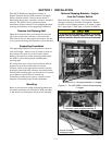
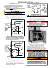
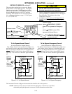
MANUAL LOAD TRANSFER
This procedure manually transfers load to other source if
the Transfer Switch or Controller are out of service.
Close enclosure doors to prevent personal
injury in case of electrical system fault.
1. Be sure thatthe BypassHandle is CLOSED oneither
Emergency or Normal (see page 3–1).
2. Be sure that the Isolation Handle is in the TEST or
ISOLA TE position (see page 3–2).
3. TurntheBypassHandlecounterclockwisetoOPEN
the Bypass Switch. Then Bypass to the other source
(see page 3–1).
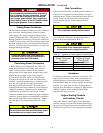
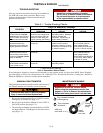
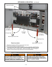
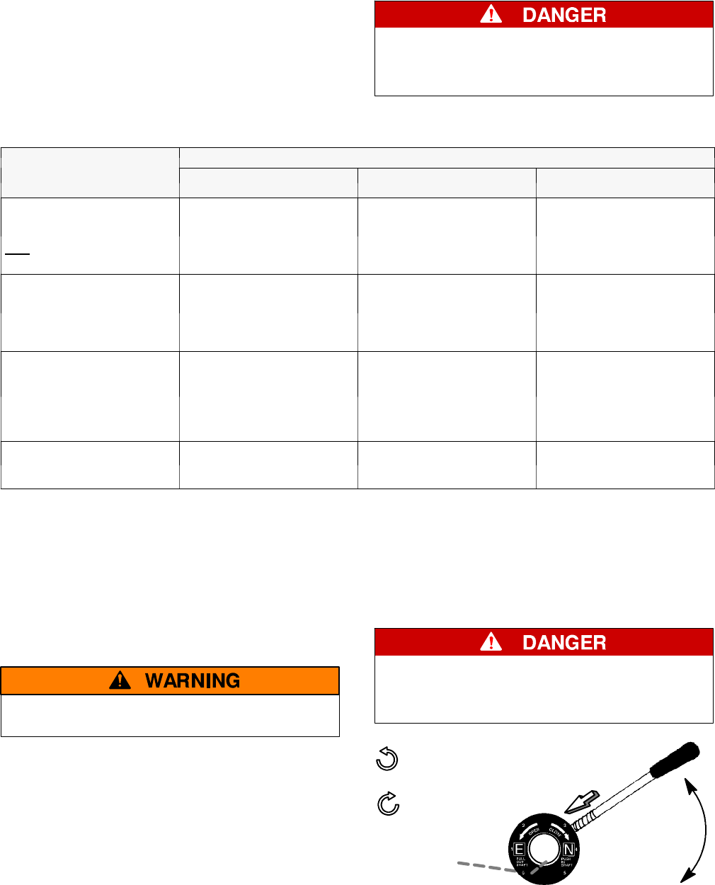
MAINTENANCE HANDLE
Bypass and isolate the Transfer Switch
before using the maintenance handle! See
pages 3–1 and 3–2. Remove the ma intenance
handle after using it and store it on the frame.
Turn counterclockwise
to Emergency.
Turn clockwise
to Normal.
insert
handle
into hole
Grasp
handle
firmly
slide hub
onto shaft