


BYPASSING & ISOLATING
(continued)
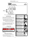
3 --- 3
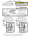
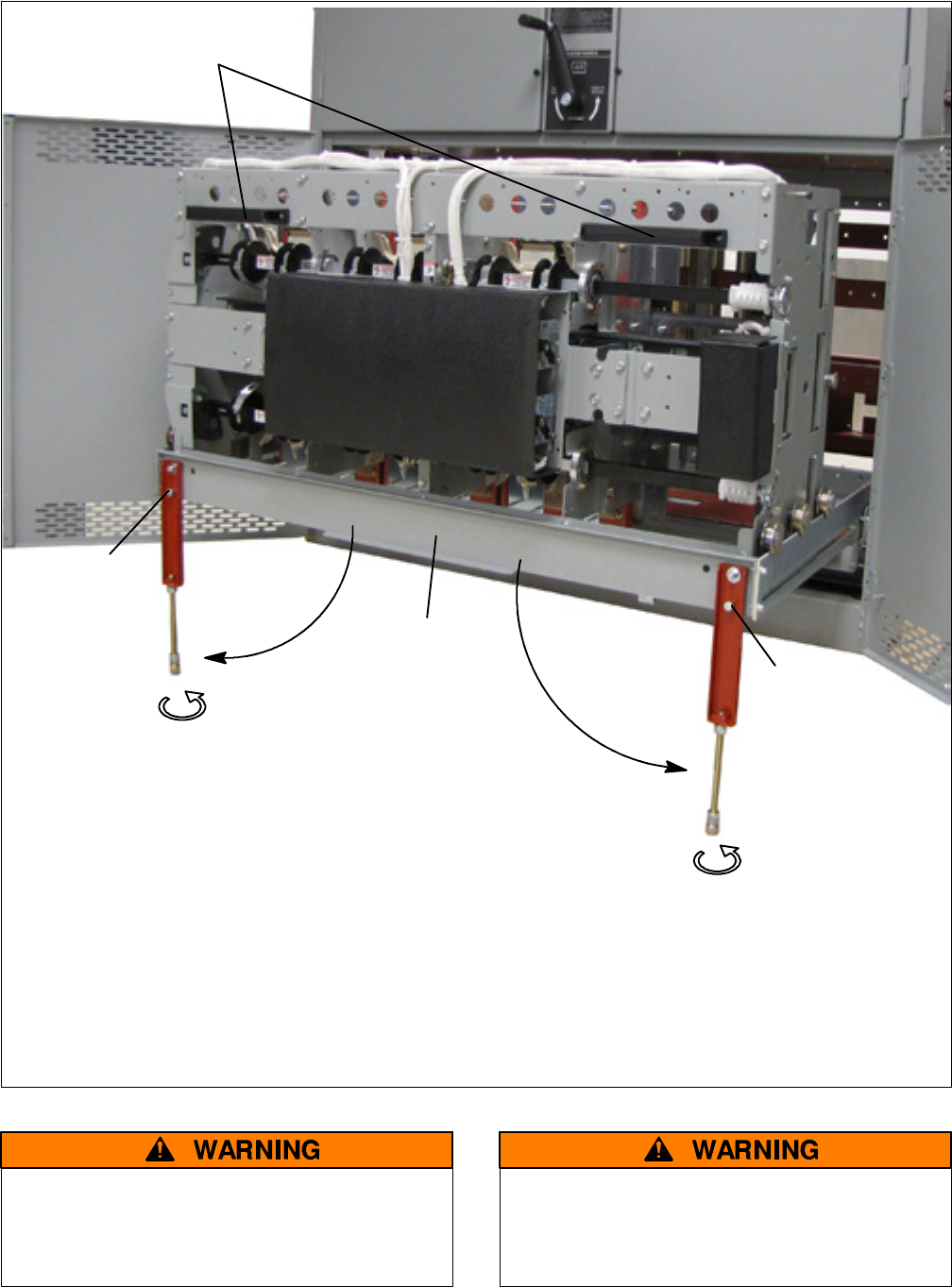
left support leg
right support leg
locking pin
with clevis pin
locking pin
with clevis pin
adjust length to touch floor
adjust length to touch floor
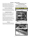
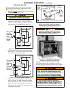
Drawout procedure
grasp tw o handles
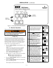
1. Bypass and Isolate the ATS, then open both lower doors.
2. Pull out the rail support carriage all the way.
3. Remove left & right clevis and locking pins, drop tw o support legs, reinstall locking
and clevis pins (to lock in place), and adjust both leg lengths to extend to the floor.
4. Stand directly in front of transfer switch. Grasp both handles, and pull straight out
(detentsontherailsrequirehighinitialforcetoovercomeresistance).
rail support
carriage
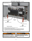
Figure 3–7b. 4000 a mp transfer switch isolated and pulled out for inspection.
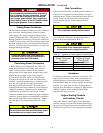
To avoid personal injury and equipment
damage on 4000 A switches, two support legs
must be extended as shown in Figure 3 –8.
Substantial initial force is required to pull out
the transfer switch (there are detents on rails).
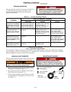
The 4000 A transfer switch weighs 600 l b.
Use lifting yoke 835745–001 o r other device
capable of lifting this weight to avoid personal
injury or equipment damage.