


INSTALLATION
(continued)
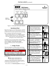
1 --- 3
observe
these lights
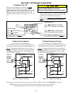
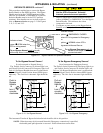
Transfer Switch
Connected
To
Normal
Transfer Switch
Connected
To
Emergency
Normal
Source
Accepted
Emergency
Source
Accepted
Transfer
Control
Retransfer
Delay
Bypass
Transfer
Test
HOLD F OR
15SECONDS
RED
RED
GREEN
GREEN
(
)
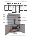
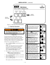
Figure 1-2. Standard controls and indicators.
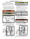
Functional Test
Read all instructions on the Wiring Diagrams and labels
affixed to the ATB. Note the control features that are
provided and review their operation before proceeding.
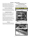
After installing the ATB check the following:
– Bypass Handle should be in the NORMAL position.
– Isolation Handle should be in the CONN position.
– TS transfer switch Normal contac ts shoul d be CLOSED
(Emergency contacts should be OPEN)
If handles are not in correct positions, follow instruc-
tions for Bypassing and Isolating the automatic transfer
switch in Section 3. Do not force the handles.
Electrical interlocks prevent a wrong sequence of
operation.
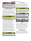
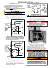
1–VoltageChecks
First check nameplate on transfer switch; rated voltage
mustbethesameasnormalandemergencylinevoltages.
Useextremecautionwhenusingameter
to measure voltages. Do not touch power
terminals; shock, burns, or death could resul t !
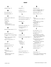
Perform steps 1–6 at the right. Observe the status lights.
See Figure 1–2.
Q Black square means light is on.
S White square means light is off.
* If n ecessary, adjust voltage regulator on generator per the
manufacturer’s recommendations. The ATB w ill respond only
to rated voltage spe c ifie d on the nameplate.
Now continue to 2 – Electrical Operation on next page.
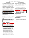
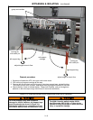
1
Close the normal source circuit
breaker. The Transfer Switch
Connected To Normal and the
Normal Source Accepted lights
should come on.
2
Use an accurate voltmeter to
check phase to phase and
phase to neutral voltages pres -
entatthetransferswitchnormal
source terminals.
3
Close the emergency source
circuit breaker. (Start generator,
if necessary.) The Transfer
Switch Connected To Normal &
Emergency Source Accepted
lights should come on.
4
Use an accurate voltmeter to
check phase to phase and
phase to neutral voltages pres -
ent a t the transfer switch emer-
gency source terminals.*
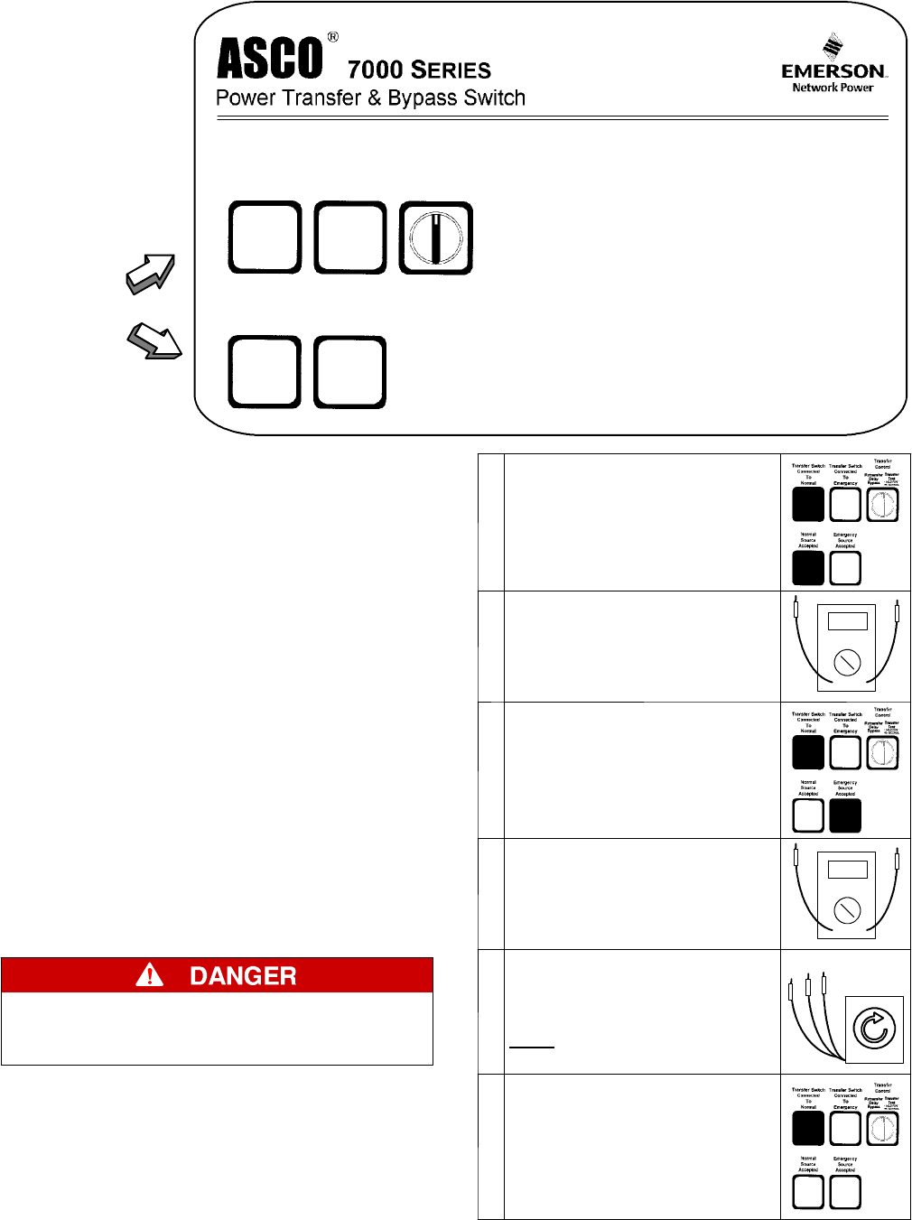
5
Useaphaserotationmeterto
check phase rotation of emer -
gency source; it must be the
same
as the normal source.
A
B
C
6
Shut down the engine–genera-
tor, if applicable. The Emergen -
cy Source Accepted light should
go off. Then put the starting
control s elector switch (on the
generator set) in the automatic
position. Close enclosure door.