


BYPASSING & ISOLATING
(continued)
3 --- 2
ISOLATING THE ATS
Isolating is required before any service work can be
performed on the automatic transfer switch (ATS).
Refer to Figures 3–4, 3–5, 3–6, and 3–7.
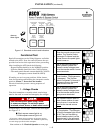
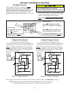
1. Bypass t he closed
automa tic transferswitchcontacts.
See BYPASSING on page 3–1.
Align position indicator. Do not leave
thehandleinanintermediateposition.
2. Turn the Isolation Handle counterclockwise
(approx. 16 turns, approx. 12 turns fo r 4000 A)
until window shows TEST.TheATScanbetested
now without load interruption (see page 2–1).
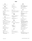
E
L
N
Automatic Transfer Switch
Bypass Switch
Turn crank
counter-
clockwise
until
window
shows
TEST.
Figure 3–4. CONNECTED to TEST position.
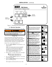
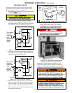
3. Continue turning Isolation Handle counterclock-
wise (approx. 7 turns, approx. 8 turns for 4000 A)
until the window shows ISOLATE.
E
L
N
Turn crank
counter-
clockwise
until
window
shows
ISOLATE.
Automatic Transfer Switch
Bypass Switch
Figure 3–5. TEST to ISOLATE position.
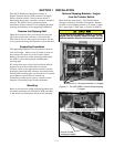
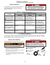
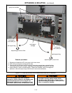
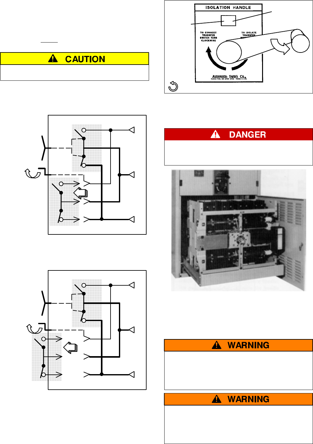
4. Open the lower enclosure door(s). Pull out the
side rail carriage. On 4000 A extend two support
legs; see Figure 3–7b. The n roll out the transfer
switch. It can be safely inspected in this position.
The transfer switch can also be removed for easier
maintenance operations.
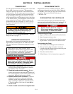
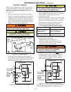
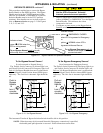
unfold
crank
position
window
CONN
TEST
ISOLATE
counterclockwise – draws out transfer switch
Figure 3–6. Isolation Handle.
NO TE: In the TEST position the transfer
switching device solenoid operator circuit is
energized through secondary disconnects.
Hazardous voltage capable of causing
electrical shock, burns, or death; do not
touch any control circuit terminals.
Figure 3–7a. 1000–3000 A transfer switch
isolated and pulled out for inspection.
See page 2–2 for maintenance handle use. For
1000–3000 A lifting yo ke kit 607064 is available to
facilitate lifting by using an overhead crane or similar
equipment . For 4000 A use lifting yoke 835745–001.
1000–3000 A switches weighs 350–450 lbs; use
lifting yoke 607064. 4000 A switches weigh
approx. 600 lb; use lifting yo ke 835745--001 o r
other device capable of lifting this weight to
avoid personal injury or equipment damage.
To avoid personal injury and equipment
damage on 4000 A switches, two support legs
must be extended as shown in Figure 3–7b.
Substantial initial force is required to pull out
the transfer switch (there are detents on rails).