


SECTION 2 TESTING & SERVICE
2 --- 1
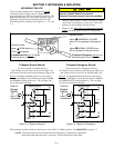
TRANSFER TEST
Test the Automatic Transfer Swi tch portion of the 7000
Series ATB at least once a month. This procedure
checks the electrical operation of the Transfer Switch
and Controller. Put the e ngine–generator starting con-
trol (at the engine–generator set) in automatic mode.
In the following test the generator will start, the load
will be transferred to the Emergency source, then back
to the Normal source. An interruption to the load will
occur, unless the the Transfer Switch contacts are by-
passed before the test. See pages 3–1 and 3–2 for by-
passing & isolating instructions if no interruption of
load is required.
Be sure to close the enclosure door before
proceeding to prevent personal injury in
case of electrical system fault.
Perform the five –step Electrical Operation – Transfer
Test procedure on page 1–4.
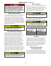
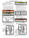
PREVENTIVE MAINTENANCE
Reasonable care in preventive maintenance will insure
high reliability and long life for the 7000 Series ATB.
An a nnual preventive maintena nce program is recom-
mended.
ASCO Services, Inc. (ASI) is ASCO P ower
Te chnologies’ national service organization. ASI
can be contacted at 1–800–800–2726 for informa-
tion on preventive maintenance agreements.
Checklist f or Yearly Inspection
Hazardous voltage capable of causing
shock, burns, or death is used in this switch.
Deenergize both Normal – Emergency power
sources before performing inspections!
S Clean the ATB enclosure. Brush and vacuum
away any excessive dust accumulation. Remove
anymoisturewithacleancloth.
S Check the transfer switch contacts
.Remove
transfer swi tch barriers and check the condition of
the contacts. Replace contacts when pitted or worn
excessively. Reinstall the barriers carefully.
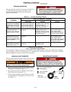
S Maintain transfer switch lubrication.Ifswitchis
sub jec ted to severe dust or abnor m al operating
conditions, renew factory lubrication on all move-
ments and linkages. Relubricate solenoid operator
if TS coil is replaced . Don’t use oil; order lubrica-
tion kit 75-100.
S Check all cable connections & retighten them.
REPLACEMENT PARTS
Replacement parts are available in kit form. When
ordering parts provide the Serial No. , Bi ll of Material
No. (BOM), a nd Catalog No. from the transfer switch
nameplate. For service call ASCO Services at
1–800–800–2726.
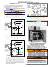
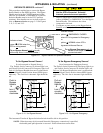
DISCONNECTING T HE CONTROLLER
The harness disconnect plugs are furnished f or repair
purposes only and should not have to be unplugged. If
the controller must be isolated, follow these steps:
Bypass–Isolation Switch is energized!
Do not touch isolation contact fingers;
shock, burns, or death could result!
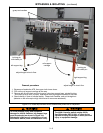
Disconnecting the Plugs
1. Bypass and Isolate the Automatic Transfer Switch.
2. Open the upper enclosure door.
3. Separate the two quick disconnect plugs by squeez-
ing the latches. Do not pull on the harness wires.
Reconnecting the Plugs
1. The ATS should be still bypassed and isolated.
2. The two harness plugs and sockets are keyed.
Caref ully align the plugs with t he sockets and press
straight in until the latches click.
3. Close the enclosure doors.
4. Follow Return to Service instructions on page 3–3.