


Installation Instructions
7
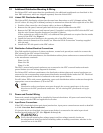
1.1.5 Floor Pedestal Installation
Floor pedestals are optional equipment that provide clearance for bottom cable entry or exit for FPC
units not installed on raised flooring. The pedestals are adjustable over a limited range (approxi-
mately 3-1/2" [89mm]) to allow leveling the FPC and minor adjustments in the unit’s installed height.
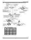
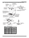
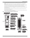
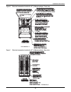
1. Insert the pedestal threaded shaft into the pedestal holes in the cabinet base as shown in
Figures 1 and 2.
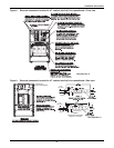
2. Adjust the pedestal height by turning the welded nut/shaft assembly into or out of the pedestal
base as required.
3. Lock the height by tightening the jam nut against the pedestal base.
The pedestal may be anchored to the floor by means of the four holes in the base. Locations of
floor pedestals are shown in Figures 1 and 2.
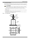
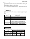
Figure 4 Floor pedestal details
!
CAUTION
Floor pedestals may be reverse-assembled for shipping. Before installation, the pedestals
should be reassembled as shown in Figure 4. When the pedestal is properly assembled, the
washer on top of the welded nut provides a bearing surface for the unit’s weight.
6"
(152mm)
square
2-1/4"
(57mm)
2-1/4"
(57mm)
2-1/4"
(57mm)
2-1/4"
(57mm)
.56" (14mm)
diameter
mounting holes
Pedestal
Base
Jam Nut
Welded Nut
Washer
Threaded
Shaft
3"
(76mm)