


Operating Instructions
32
To Set Unit Clock - To set the clock from the unit front panel, simultaneously press the Scan and
Hold membrane switches while the time and date screen is displayed on the LCD. A cursor should
appear on the selected time and date field. Use the Scan switch to increment the highlighted field and
the Hold switch to decrement the highlighted field. Use the Silence push button to select the next
time and date field. The time can be displayed in AM/PM or 24-hour format. Simultaneously press the
Scan and Hold switches to exit the clock set screen.
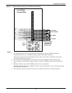
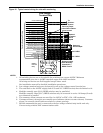
RS-232 ASCII Communications Port - Units with power monitoring are equipped with an isolated
RS-232 ASCII Communications Port, which allows access to unit monitored parameters and alarm
information. The RS-232 port connections are located on the low voltage control terminal strip inside
the unit. See typical control wiring in Figure 16.
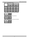
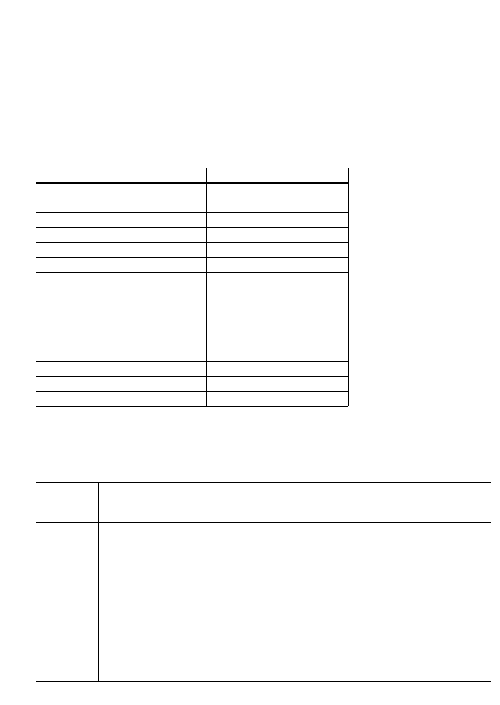
The ASCII interface default parameters are shown in Table 15.
The ASCII port uses a Query-Response Format.
Table 17 shows the list of available customer commands. Only one command is serviced at a time.
Valid commands are terminated with a carriage return [0Dh]. Commands are accepted in upper or
lower case. Responses are in upper case, terminated with a line feed [0Ah] and carriage return [0Dh].
Table 15 ASCII interface default parameters
Parameter Default
Interface RS-232 using EIA voltage levels
Baud rate 9600
Parity None
Data bits 8
Stop bits 1
Terminator <CR>
Hand shaking Not supported
Structure Half-duplex
Echo OFF
Change to receive after transmit 1.28 msec
Minimum delay to transmit after receive 120 µsec
Maximum response time turn around 300 msec
Maximum response completion time 500 msec
Minimum delay between commands 500 msec
Maximum intercharacter delay 12.5 msec
Table 16 RS-232 ASCII port customer commands
Command Description Typical Response
Time? <CR>
Date? <CR>
Unit: Time
Unit: Date
03:40:37A<LF><CR>
05-15-97<LF><CR>
UID? <CR>
kVA? <CR>
V? <CR>
Unit ID
Nominal kVA
Nominal L-L Voltage
Unit_No._PDU_21B____<LF><CR>
0150<LF><CR>
0208<LF><CR>
SS1? <CR> System Information
(20-character fields
with comma separators)
UNIT_MODEL_NUMBER___SERIAL NUMBER_______
SITE_ID_NUMBER______TAG_NUMBER__________<LF><CR>
SA? <CR> Number of Active Alarms
(20-character alarms
with time stamp)
02, OUTPUT_OVERVOLTAGE__05-15-97,01:25:30A
OUTPUT_OVERCURRENT__05-15-97,01:27:46A<LF><CR>
UPMD?
<CR>
Monitored Parameters
(32 comma-separated
data fields—see
Table 17 for descriptions
of field positions)
0484,0485,0483,0210,0212,0211,0121,0122,0121,0068,
0085,0120,0131,0018,0030,0092,0033,0600,0038,0041,
0043,0549,0632,0599,0000,1528,0018,0019,0020,0045,
0047,0049,0044<LF><CR>