


17
COMMUNICATIONS
Do not exceed NEC Class 2 limits for any connection to the DB-25 connector on the Relay
Interface card, the DB-9 communication port, and the EPO connector.
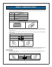
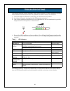
Relay Interface Card
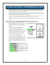
Your GXT5000R-208 comes equipped with the RELAYCARD-INT relay card. Connections
must not exceed NEC Class 2 limits.
The Intellislot
®
Interface for Relay Contacts card provides contact closures for remote moni-
toring of alarm conditions in your Liebert UPS, delivering signals for On Battery, On Bypass,
Low Battery, Summary Alarm, UPS Fault and On UPS.
The contacts are rated for 24 VAC or DC at 1A.
Pin Configuration
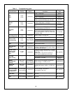
Table 1 Pin configuration
Pin Function Operation
1 UPS Fault Closed if no UPS failure
2 Not Used —
3 Not Used —
4 UPS Fault Closed if UPS fails
5 Summary Alarm* Closed if SUMMARY ALARM* occurs
6 Summary Alarm* Closed if no alarm conditions are present
7 Signal Ground (for UPS Any Mode Shutdown)
8 Not Used —
9 Common – Low Battery
10 Low Battery Closed if battery is OK
11 Low Battery Closed if LOW BATTERY point occurs.
12 Not Used —
13 Not Used —
14 UPS Any Mode Shutdown (short to pin 7) Not utilized on GXT5000R-208 - See EPO section
15 On UPS Closed if ON UPS (inverter) power
16 On Battery Closed if ON BATTERY power (Utility failure)
17 Common – UPS Fault, Summary Alarm,
On UPS, On Battery, On Bypass
18 On Battery Closed if not ON Battery power (Utility OK)
19 Not Used —
20 Not Used —
21 Not Used —
22 Not Used —
23 Not Used —
24 On Bypass Closed if ON BYPASS
25 Not Used —
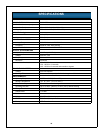
A Summary Alarm occurs when any of the following four conditions exist:
1. Utility power is out of the acceptable range (voltage and/or frequency).
2. UPS is in BYPASS MODE (load not on Inverter power).
3. UPS Battery is LOW (< 2 minutes of battery power remaining).
4. UPS fault has occurred.