LEDs Controls, LEDs and Connectors
RTM-ATCA-7350 Installation and Use (6806800H30F)
39
The GE daughter card provides the network port indicators and the FC daughter card provides
the FC status indicators. You can monitor these indicators to diagnose the current status of
RTM-ATCA-7350.
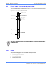
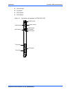
The following table lists the indicators on the RTM-ATCA-7350 face plate.
Table 3-1 Indicators on the RTM-ATCA-7350 Face Plate
Indicator Color Meaning Description
OOS Red or amber Service status
indicator
z The RTM-ATCA-7350 turns the red LED on
when transitioning from FRU M3 to M4
state if in local control state. It is the
responsibility of the application to change
the status of the LED via IPMI command.
z The RTM-ATCA-7350 turns the LED off
when transitioning from FRU state M6 to
M1 if in local control state.
IS Red, green or
amber
In service indicator The IS LED is off when the payload processor
starts running.
Payload Management software is
responsible for controlling the IS LED.
H/S Blue Hot swap indicator z Off: RTM-ATCA-7350 is in activated state.
z On: RTM-ATCA-7350 is inserted, but in
deactivated state or not powered on.
z Blinking at the long blink rate
1
: RTM-ATCA-
7350 is requesting activation.
z Blinking at the short blink rate
2
: RTM-
ATCA-7350 is requesting deactivation.
1. Blinking at the long blink rate means that the indicator is on for 900 ms and then off for 100 ms alternatively.
2. Blinking at the short blink rate means that the indicator is on for 100 ms and then off for 900 ms alternatively.
ATN Amber Attention indicator The ATN LED is set to off when the payload
processor starts running.
Payload Management software is responsible
for controlling the ATN LED.


