4
RTM-ATCA-7350 Installation and Use (6806800H30F)
47
Functional Description
4.1 Overview
This chapter describes:
z Block diagram
z Daughter cards
4.2 Block Diagram
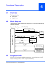
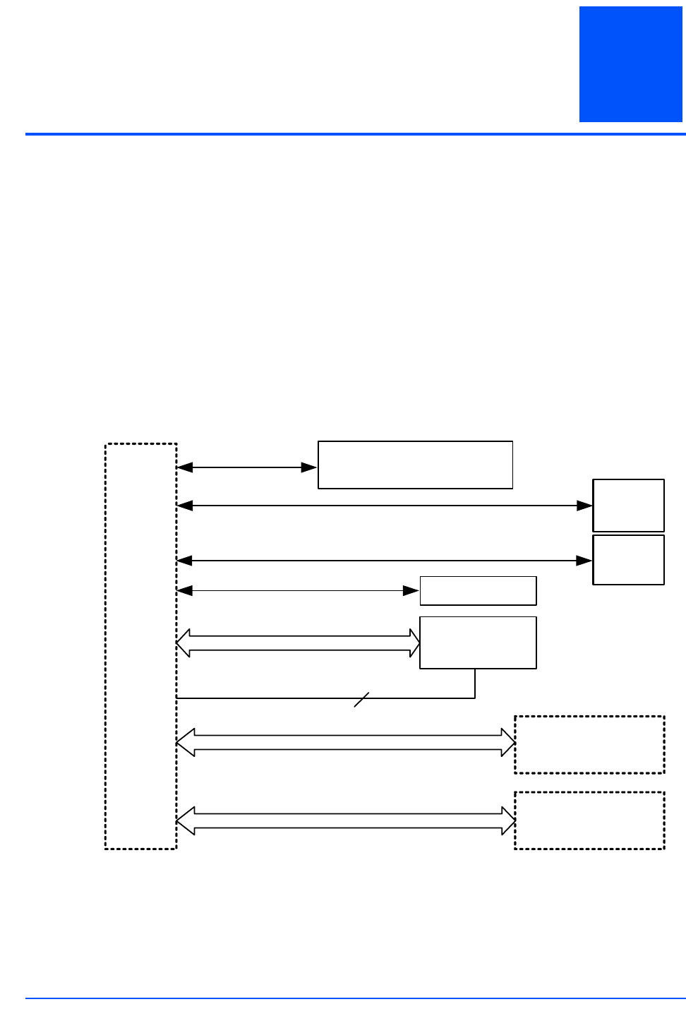
The following block diagram shows the main components of RTM-ATCA-7350 and how they
interact/are connected.
4.3 Daughter Cards
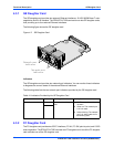
RTM-ATCA-7350 provides two daughter card connectors, you can choose one or two GE
daughter cards (single slot) or one FC daughter card (dual slot).
Figure 4-1 Block Diagram of RTM-ATCA-7350
Zone3(P30&P31&P32)
EEPROM (SDR & FRU)
LM80
USB
Port
VGA
Port
Power
Supply
Mezzanine 1
(Connector:J2)
Mezzanine 2
(Connector:J1)
IIC
USB1.1
VGA
5VSBY & 12V & 3.3V
2GB/s
PCI-EX4
2GB/s
PCI-EX4
BCM57710
10GB/s
PCI-EX4*2
P0,P1,P2,P3


