


Installation Drawings
32
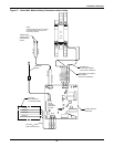
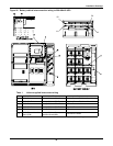
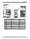
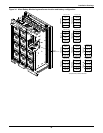
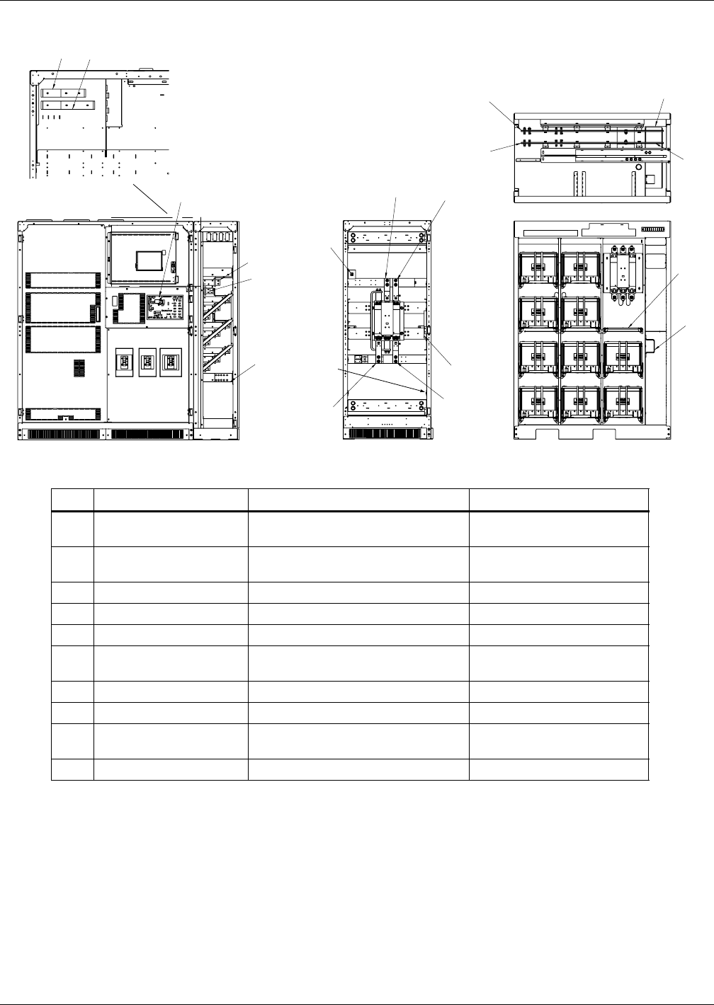
Figure 30 Liebert NXL UPS to Liebert NXL Module Battery Disconnect to Liebert NXL Battery Cabinet
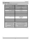
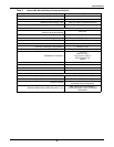
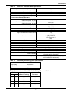
Table 5 Liebert-supplied interconnect wiring
Run From To Conductors
A1 UPS - DC+ Busbar MBD - DC+ Busbar
Positive Power - RH Mount/
Stand-Alone
B1 UPS - DC- Busbar MBD - DC- Busbar
Negative Power - RH Mount/
Stand-Aone
A2 UPS - DC+ Busbar MBD - DC+ Busbar Positive Power - Left Mount
B2 UPS - DC- Busbar MBD - DC- Busbar Negative Power - Left Mount
C* UPS - Ground MBD - Ground Ground
D
UPS - External Interface
Board (EIB)
MBD - Battery Interface Board (BIB) CAN Control Cables
E MBD - DC+ Busbar Battery Cabinet - DC+ Busbar Positive Power
F MBD - DC- Breaker Battery Cabinet - DC- Busbar Negative Power
G
MBD - Battery Interface
Board (BIB)
Battery Cabinet - Battery
Interface Board (BIB)
CAN Control Cables
H* MBD - Ground Battery Cabinet - Ground Ground
* For detached units only
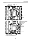
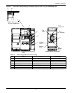
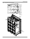
Top FeedA1, A2, E
F, B1, B2
C,H
Top
Feed
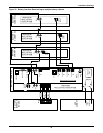
D,G
G
H
F
E
A1
B1
C
D
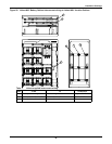
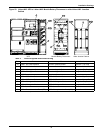
UPS - Rear View
DC Bus Connections
F
E
B1,2
Bottom
Feed
F
C,H
Bottom
Feed
Bottom
Feed
A1,2,E
A2
B2
Top
Feed
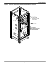
UPS
Battery Cabinet
Modular Battery Disconnect