


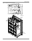
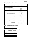

Installation Drawings
35
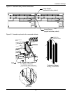
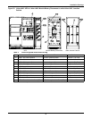
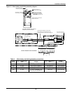
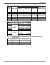
Figure 33 Alber battery monitoring assembly diagram
Table 6 Alber battery monitoring assembly connections
Input
Voltage
Alber Transformer-2
(Wht) Jumper
Alber Transformer-1
(Blk)
F4-F5
Fuse Rating
600 0 (Top) 300 (Top) to 0 (Bottom) 300 (Bottom) 2.25 A, 600VAC
480 0 (Top) 240 (Top) to 0 (Bottom) 240 (Bottom) 1.25 A, 600VAC
380 0 (Top) 300 (Top) to 208 (Bottom) 300 (Bottom) 1 A, 600VAC
208 0 (Top)
0 (Top) to 0 (Bottom) and
208 (Top) to 208 (Bottom)
208 (Top) 0.75A, 600VAC
F76
F75
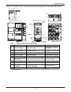
NXL BATTERY CABINET
UPS MODULE OUTPUT
XFMR CONNECTION DIAGRAM
Harness factory-installed.
Verify transformer connection
Prior to startup.
See diagram below.
.
.
ALBER BATTERY
MONITORING XFMR
This harness is intended for use only when
battery cabinet is connected directly to UPS.
For all other instances, customer must supply wire.
TOP TERMINALS
FROM F5 FUSE IN BAT CAB
BOTTOMTERMINALS
FROM F4 FUSE IN BAT CAB
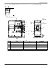
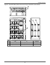
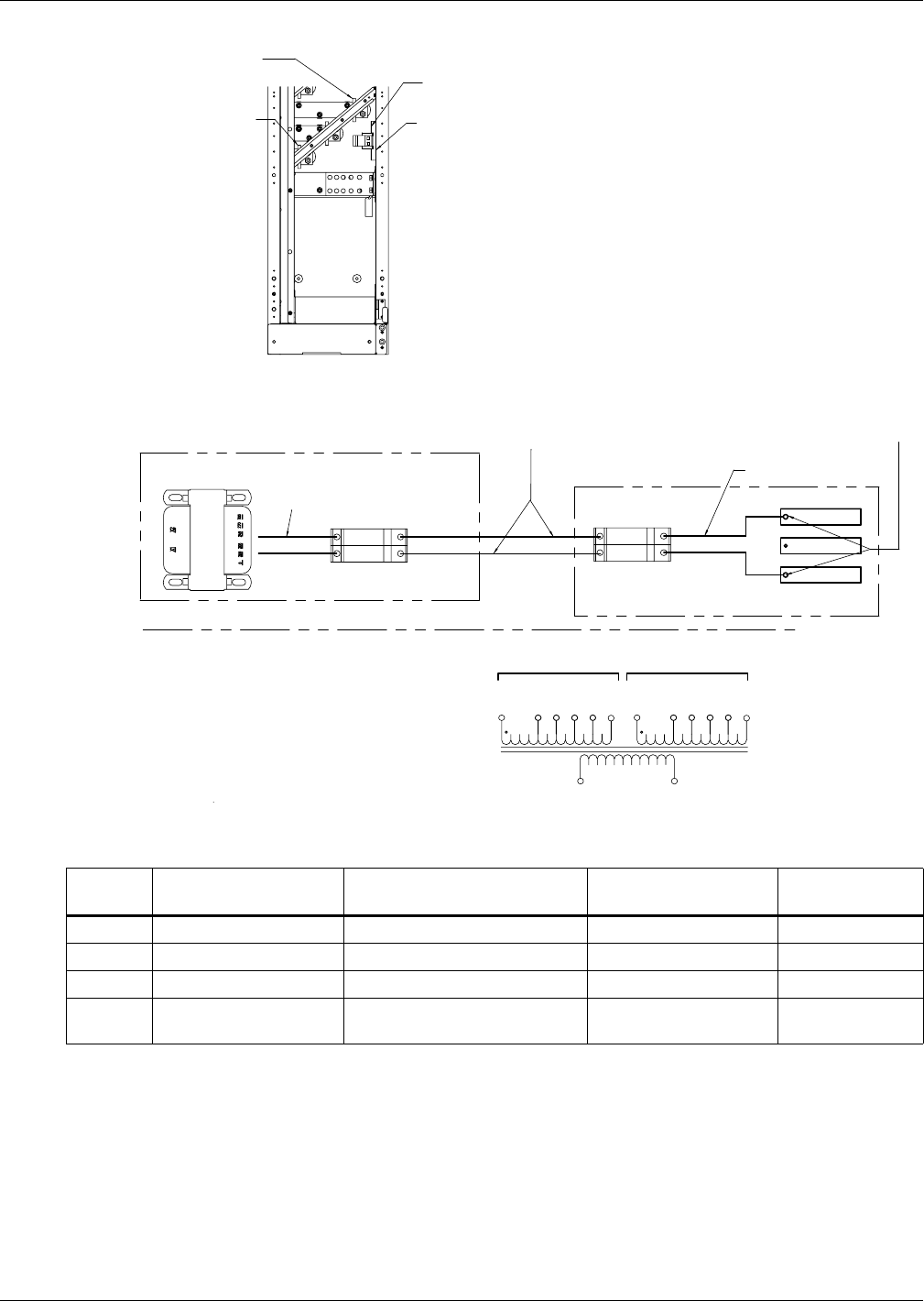
250, 300, & 400 KVA UPS MODULE
FUSEBLOCK INSTALLATION
F5
F4
Mount fuses to corner post
in input/output compartment
of UPS module. Choose best
location based on bottom or top
power cabling.
UPS Output - Phase A
Use Pilot Hole on Busbar.
UPS Output - Phase C
Use Pilot Hole on Busbar.
V_OUT_A
V_OUT_C
Wire Harness
Secure supplied wire harness
to busbar with supplied hardwa
r
Locate fuse label as
close to fuses as possible
Connect cables from UPS output
busbars to fuse block
X1
X2
0 V
270 V
208 V
240 V
300 V
200 V
0 V
270 V
208 V
240 V
300 V
200 V
230 V