


Connecting to the Network
Matrix DFE-Platinum Series Installation Guide 3-7
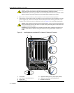
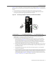
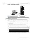
Figure 3‐3showsconnectingatwistedpairsegmenttothe2G4082‐25module.Itisassumedthat
thechassispoweristurnedontoprovidepowertothemodule.RefertoFigure 3‐3andproceedas
follows:
1. Ensurethatthedeviceconnectedtotheotherendofthesegmentispowered
ON.
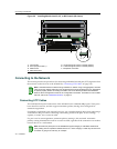
2. ConnectthetwistedpairsegmenttothemodulebyinsertingtheRJ45connectoronthe
twistedpairsegmentintotheappropriateRJ45portconnector.
Figure 3-3 Connecting a Twisted Pair Segment to the DFE-Platinum Module
3. VerifythatalinkexistsbycheckingthattheportRX(Receive)LEDisON(flashingamber,
blinkinggreen,orsolidgreen).IftheRX
LEDisOFFandtheTX(Transmit)LEDisnot
blinkingamber,performthefollowingstepsuntilitison:
a. Toviewthereceiveandtransmitactivityonagroupofsegments,presstheGROUP
SELECTbutton(seeFigure 3‐3)tosteptothegroupofinterest(Groups1and2).
Each
timetheGROUPSELECTbuttonispressed,theGROUPLEDlightsupinsequence,
indicatingwhichGroupisselected.Thereceiveandtransmitactivityforthatgroupof
segmentsisthenindicatedbytheRXandTXLEDsforeachsegment.
b. VerifythatthecablingbeingusedisCategory5
UTPwithanimpedancebetween85and
111 ohms. Fortheporttooperateat100or1000Mbps,Category 5cablingmustbeused
andinstalledproperly.
c. Verifythatthedeviceattheotherendofthetwistedpairsegmentisonandproperly
connectedtothesegment.
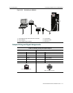
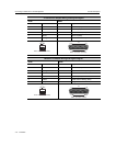
d. VerifythattheRJ45
connectorsonthetwistedpairsegmenthavetheproperpinoutsand
checkthecableforcontinuity.Typically,acrossovercableisusedbetweenhubdevices.A
straight‐throughcableisusedtoconnectbetweenswitchesorhubdevicesandanend
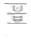
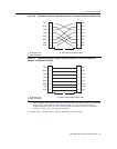
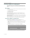
user(computer).RefertoFigure 3‐4andFigure 3‐5for
four‐wireRJ45connections.Refer
toFigure 3‐6andFigure 3‐7foreight‐wireRJ45connections.
1 RJ45 connector 2 RJ45 port connector (port 1) 3 GROUP SELECT button
Â
COM
OFFLINE/
RESET
MGMT CPU
1
2
GROUP
SELECT
1X
11X 12X
G
R
O
U
P
1
GROUP
1
2
3
4
5
6
7
8
9
10
11
12
2G4082-25
Gb ENET
RX
TX
Á
À