


Figures ix
Figures
Figure Page
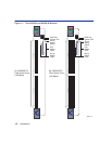
1-1 The 6H308-24 and 6H308-48 Modules...........................................................................1-2
3-1 Installing the Module into the MATRIX E7 Chassis.........................................................3-4
3-2 Installing the Module into the 6C105 Chassis .................................................................3-6
3-3 Connecting a Fiber Optic Segment to the Module ..........................................................3-8
4-1 LANVIEW LEDs ..............................................................................................................4-1
4-2 RESET Button .................................................................................................................4-7
B-1 Mode Switch Location .....................................................................................................B-2
B-2 FLASH Module Location .................................................................................................B-4
B-3 Installing the FLASH........................................................................................................B-5