


Connecting to the Network
Installation 3-7
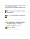
3.5 CONNECTING TO THE NETWORK
This section provides the procedures for connecting fiber optic cable from the network or other
devices to the module. For details on how to get manuals, refer to the “Related Documents” section
in About This Guide.
The front panel ports of the module are 100BASE-FX, MT-RJ ports.
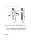
Connect a fiber optic cable segment to the module as follows:
1. Remove any protective covers from the fiber optic ports on the applicable port on the module
and from the ends of the connectors on the cable segment.
2. Insert one end of the cable with an MT-RJ connector into the appropriate port on the module.
The MT-RJ connector is keyed with a self-locking tab. See Figure 3-3.
3. At the other end of the fiber optic cable, attach the MT-RJ connector to the other device.
NOTE: If the module is being installed in a network using SmartTrunking, there are
rules concerning the network cable and port configurations that must be followed for
SmartTrunking to operate properly. Before connecting the cables, refer to the
MATRIX
E7 Series and SmartSwitch 6000 Series Modules Local Management User’s Guide
for
the configuration information.
NOTE: An odd number of crossovers (preferably one) must be maintained between
devices so that the transmit port of the other device and vice versa.
CAUTION: Do not touch the ends of the fiber optic strands, and do not let the ends
come in contact with dust, dirt, or other contaminants. Contamination of the ends
causes problems in data transmissions. If the ends become contaminated, blow the
surfaces clean with a canned duster. A fiber port cleaning swab saturated with
optical-grade isopropyl alcohol may also be used to clean the ends.
NOTE: To remove an MT-RJ connector, you press on its locking tab to release it and
pull it out of the front-panel connector.