


Installing Module into Matrix E7 or Matrix N7 Chassis
3-8 Installation
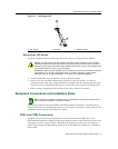
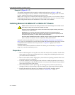
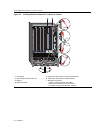
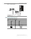
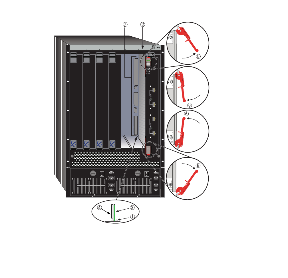
Figure 3-2 Installing Module into Matrix E7 or Matrix N7 Chassis
1 Card guides 5 Upper/lower locking tabs (in proper open position)
2 Slot number 6 (left-most slot is 1) 6 Upper/lower locking tab (in closed position)
3 Module 7 Backplane connectors
4 Metal back panel - Top two connectors (power and FTM2)
- Bottom two connectors (power and FTM1)
(no bottom connectors in Matrix N7 chassis)