COM Port Pinout Assignments
Matrix DFE-Platinum Series Module Installation Guide A-3
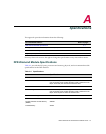
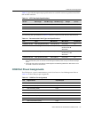
Table A‐3providestheinput/outputspecificationsforeachXFPversionasspecified intheIEEE
802.3ae‐2002standard.
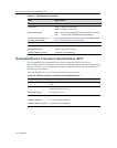
ThefollowingXFPspecificationsinTable A‐4meetorexceedtheIEEE802.3ae‐2002standard.
COM Port Pinout Assignments
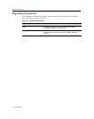
TheCOMportisaserialcommunicationsportforlocalaccesstoLocalManagement.Referto
Table A‐5fortheCOMportpinassignments.
Table A-3 XFP Fiber-Optic Specifications
Module Wavelength
Tx Power
Min/Max (avg.)
Rx Sensitivity
Min/Max (avg.)
Link Power
Budget
MTBF
(hours)
10GBASE-LR-XFP 1310 nm DFB -8.2 / 0.5 dBm -14.4 / 0.5 dBm 9.4 dB 2,631,579
10GBASE-ER-XFP 1550 nm EML -4.7 / 4.0 dBm -15.8 / -1.0 dBm 15 dB 2,000,000
10GBASE-ZR-XFP 1550 nm EML 0 / 4.0 dBm -25 / -7.0 dBm 18 dB 1,164,047
10GBASE-SR-XFP 850 nm VCSEL -7.3 / -1.0 dBm -9.9 / -1.0 dBm 7.3 dB 4,081,633
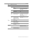
Table A-4 Recommended Cable Types and Specifications
Item Type Max. Reach
Min. Reach
1
1. The limiting factor is saturation of the receiver by the transmitter. When presented with a signal at a strength
above the saturation point, the receiver cannot distinguish between pulses, though no hardware damage
occurs.
Connector
10GBASE-LR-XFP SMF (Single Mode Fiber) 10 km (6.21 mi) 2 m (6.6 ft) LC
10GBASE-ER-XFP SMF (Single Mode Fiber) 40 km (24.85 mi)
2
2. Links longer than 30 km for the same link power budget are considered engineered links. Attenuation for such
links needs to be less than the minimum.
2 m (6.6 ft) with
minimum of 5 dB
attenuation
LC
10GBASE-ZR-XFP SMF (Single Mode Fiber) 80 km (49.7 mi) 2 m (6.6 ft) with
minimum of 11 dB
attenuation
LC
10GBASE-SR-XFP MMF (Multimode Fiber) 300 m (984 ft) 2 m (6.6 ft) LC
Table A-5 COM Port Pin Assignments
Pin Signal Name Input/Output
1 Transmit Data (XMT) Output
2 Clear to Send (CTS) Input
3 Data Set Ready (DSR) Input
4 Receive Data (RCV) Input
5 Signal Ground (GND) NA
6 Request to Send (RTS) Output
7 Data Terminal Ready (DTR) Output
8 Data Carrier Detect (DCD) Input


