


Installing the Chassis into a Rack
Enterasys NAC Controller Hardware Installation Guide 3-3
Wheninstallingtheswitchonaflatsurface,theinstallationoftherubberfeetisrecommendedto
preventtheswitchfromslidingonaflatsurface.Installingtherubberfeetisoptionalifyouare
installingtheswitchinarack.Toinstalltherubber feet,proceedto“InstallingtheRubber
Feet”
instructionsbelow.Forinstructionstorackmountthesw itch,proceedto“InstallingtheChassis
intoaRack”onpage3.
Installing the Rubber Feet
Toinstalltherubberfeetproceedasfollows:
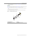
1. Placetheswitchonitsbackonasturdyflatsurfacetogainaccesstothebottomofthechassis.
2. Removethefourrubberfeetfromtheirplasticbagintheshippingbox.
3. Locatethefourmarkedlocationsonthebottom fourcornersof
thechassis.
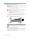
4. Removetheprotectivestripfromthebackofonerubberfootandpositionitonamarked
locationandpressfirmlyintoplace.Repeatthisproceduretoinstalltheremainingthree
rubberfeetintheotherthreelocations.
5. Afterinstallingtherubberfeet,returntheswitchtoitsuprightposition.
6. Forarackmountinstallation,proceed to “InstallingtheChassisintoaRack”onpage3.
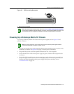
Installing the Chassis into a Rack
TheEnterasys Matrix N1Chassiscan bemountedinastandardEIA‐310‐Dcompliant
48.26‐centimeter(19‐inch)equipmentrack.Tomountthechassisintoarackyoumustallowat
least60centimeters(24inches)ofclearanceinfrontoftherackforchassisinstallation.Thendecide
whethertoinstallthe
chassisonashelfintherack,ortoattachthechassisdirectlytotherack.
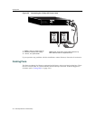
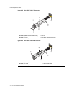
Installing the Chassis on the Rack Shelf
Toinstallthechassisonarackshelf:
1. KeepingtheaboveCautionnoteinmind,locatethepositionontherackwhereyouwillinstall
theshelf.
2. Referto“InstallingtheRubberFeet”onpage3.
3. Alignthefourholesintheearsoftheshelfwiththoseintherack,
thenfastentheshelftothe
rackusingfourofthescrewssuppliedwiththerack.
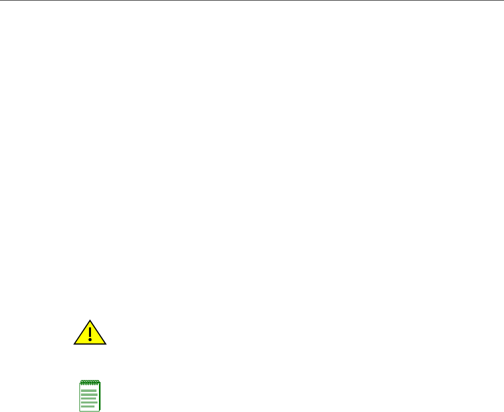
4. Afterinstallingtheshelf,proceedtoinstalltheEnterasys Matrix N1Chassisasdescribedin
“InstallingtheChassisDirectlytotheRack”onpage4.
Caution: Read Chapter 2 before completing the following procedure to ensure that all installation
guidelines are met.
Precaución: Antes de llevar a cabo el siguiente procedimiento, lea Chapter 2 para y asegúrese de
cumplir con todos los requisitos de instalación.
Note: In order to prevent a possible interference between the rack frame front and chassis rack
ears, the tapped rails may need to be adjusted such that they are recessed approximately 2 inches
behind the rack frame front. If the rack has a front door, this distance may need to be slightly more
depending on the door thickness.