


Connecting to the Network
Matrix DFE-Gold Series Installation Guide 3-15
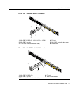
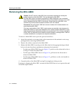
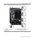
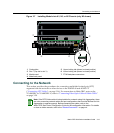
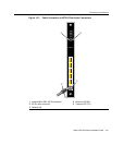
Figure 3-7 Installing Module into N1, N3, or N5 Chassis (only N3 shown)
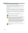
Connecting to the Network
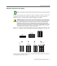
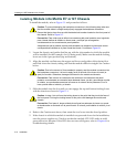
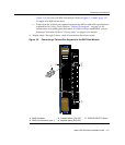
Thissectionprovidesthe proceduresforconnectingunshieldedtwistedpair(UTP)
segmentsfromthenetworkorotherdevicestothe4G4282‐49and4G4202‐72
(“ConnectingUTPCables”onpage 3‐16).ForconnectionstoMini‐GBICportsonthe
7G‐6MGBICor7G‐6MGBIC‐A,referto“ConnectingFiber‐
OpticCablestoMini‐GBICs”
onpage 3‐20.
1 Card guides 5 Upper locking tab (shown in closed position)
2 Slot 1 (Top slot is slot 3.) 6 Lower locking tab (shown in closed position)
3 Module card 7 FTM2 backplane connectors
4 Metal back panel
FAN
STATUS
7C203-1
REDUNDANCY
PWR
100-125V~12.0A
200-240V~6.0A
50/60 Hz
0
7C203-1
REDUNDANCY
PWR
100-125V~12.0A
200-240V~6.0A
50/60 Hz
0
COM
OFFLINE/
RESET
GROUP 3
GROUP 1 GROUP 2
CPU
MGMT
GROUP
123
GROUP
SELECT
1X
6X
7X
12X
13X
18X
19X
24X
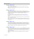
7G4202-72
Gb ENET
Á
Æ
Ä
Â
ÀÃ
Å
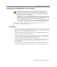
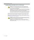
Note: If the DFE-Gold module is being installed in a network using Link Aggregation, there
are rules concerning network cables and port configurations that must be followed for Link
Aggregation to operate properly. Before connecting the cables, refer to the
Matrix DFE-Gold Series Configuration Guide for the configuration information. For details
on how to obtain manuals, refer to the “Related Documents” on page xiv
.