


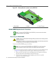

Memory Locations and Replacement Procedures
B-6 Mode Switch Bank Settings and Optional Installations
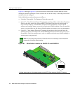
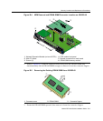
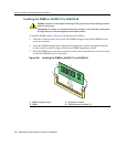
Installing the DRAM SIMM on 4G4282-49
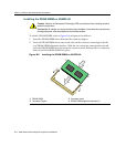
ToinstallaDRAMSIMM,refertoFigure B‐6and proceedasfollows:
1. InserttheDRAMSIMMdownbetweentheconnectorfingers.
2. PivottheDRAMSIMMdownwardsothetabsontheconnectorarmsalignwiththe
twoDRAMSIMMalignmentnotches.Withthetwoconnectorarmsspreadoutward,
pushtheDRAM
SIMMdownbetweentheconnectorarms.Releasethetwoconnector
armstolocktheDRAMSIMMintoplace.
Figure B-6 Installing the DRAM SIMM on 4G4282-49
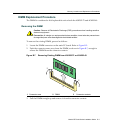
Caution: Observe all Electrostatic Discharge (ESD) precautions when handling sensitive
electronic equipment.
Precaución: Al trabajar con equipos electrónicos sensibles, tome todas las precauciones
de seguridad para evitar descargas de electricidad estática.
1 DRAM SIMM 3 Connector arms
2 Connector fingers 4 DRAM SIMM alignment notches (2)
À
Á
Â
Ã
Ã
Â